RM27M0U
_51
Engine / Hybrid System
_049111
3UR-FBE COOLING
_0234053
THERMOSTAT
A
3UR-FBE COOLING THERMOSTAT INSTALLATION
PROCEDURE

 16031
1.INSTALL WATER INLET SUB-ASSEMBLY WITH THERMOSTAT
a.
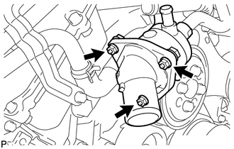
Install a new gasket and the water inlet with thermostat with the 3 nuts.
- Torque:
- 10 N*m (102 kgf*cm, 7 ft.*lbf)
b.
0.494,2.555 1.038,2.704
0.544,0.149
10
RH Side
1.214,2.896 1.564,3.045
0.350,0.149
10
Front
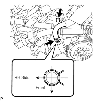
Install the air tube bracket bolt.
- Torque:
- 10 N*m (102 kgf*cm, 7 ft.*lbf)
c.
Connect the No. 5 water by-pass hose.
- HINT:
-
Install the hose so that the direction of the hose clamp is as indicated in the illustration.
d.
0.792,0.135 0.625,0.135
0.625,0.135 0.385,1.01
false
1.375,1.917 2.135,1.542
2.135,1.542 2.385,1.542
false
2.427,1.448 3.135,1.656
0.708,0.208
10
true
No. 2 Hose
0.813,0.052 1.573,0.26
0.76,0.208
10
true
No. 3 Hose
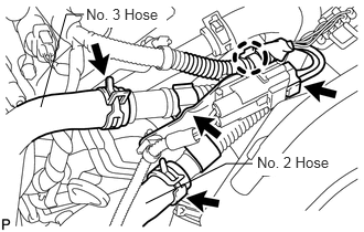
Connect the air pump connector clamp's holder.
e.
Attach the wire harness clamp.
f.
Connect the air pump connector.
g.
Connect the No. 2 and No. 3 air hoses.
16572
2.CONNECT OUTLET RADIATOR HOSE
3.ADD ENGINE COOLANT
4.INSPECT FOR COOLANT LEAK
11209
5.INSTALL V-BANK COVER SUB-ASSEMBLY
51441
6.INSTALL NO. 1 ENGINE UNDER COVER