Home › Drivetrain › TIRE AND WHEEL › TIRE PRESSURE WARNING SYSTEM
RM27M0U _52 Drivetrain _049120 TIRE AND WHEEL _0234088 TIRE PRESSURE WARNING SYSTEM J

TIRE AND WHEEL  TIRE PRESSURE WARNING SYSTEM  ECU Power Source Circuit  


DESCRIPTION

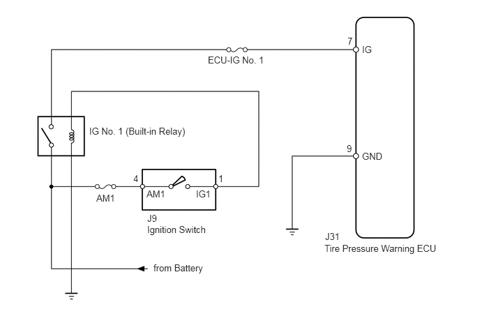
This is the power source for the tire pressure warning ECU.

WIRING DIAGRAM
C230141E03
2.198,3.344 3.135,3.552 0.938,0.208 10 false Ignition Switch 2.188,2.813 2.583,2.969 0.396,0.156 10 false AM1 2.927,2.813 3.26,3 0.333,0.188 10 false IG1 1.99,2.583 2.135,2.771 0.146,0.188 10 false 4 1.333,1.875 2.885,2.125 1.552,0.25 10 false IG No. 1 (Built-in Relay) 3.26,2.583 3.448,2.771 0.188,0.188 10 false 1 3.104,0.813 4.094,1.042 0.99,0.229 10 false ECU-IG No. 1 1.438,2.875 1.74,3.042 0.302,0.167 10 false AM1 5.188,0.531 5.417,0.729 0.229,0.198 10 false 7 5.177,2.135 5.375,2.333 0.198,0.198 10 false 9 5.406,0.656 5.635,0.823 0.229,0.167 10 false IG 5.406,2.25 5.781,2.479 0.375,0.229 10 false GND 2.292,3.917 3.115,4.146 0.823,0.229 10 false from Battery 4.844,3.625 6.625,3.813 1.781,0.188 10 false Tire Pressure Warning ECU 4.854,3.448 5.229,3.625 0.375,0.177 10 false J31 2.198,3.177 2.531,3.365 0.333,0.188 10 false J9

CAUTION / NOTICE / HINT

NOTICE:
·

When replacing the tire pressure warning ECU, read the transmitter IDs stored in the old ECU using the Techstream and write them down before removal.

·

It is necessary to perform initialization (See page Drivetrain>TIRE AND WHEEL>TIRE PRESSURE WARNING SYSTEM>INITIALIZATION) after registration (See page Drivetrain>TIRE AND WHEEL>TIRE PRESSURE WARNING SYSTEM>REGISTRATION) of the transmitter IDs into the tire pressure warning ECU after the ECU and/or tire pressure warning valve and transmitter has been replaced.


PROCEDURE

1.INSPECT FUSE (ECU-IG No.1)
a.

Remove the ECU-IG No. 1 fuse from the main body ECU.


b.

Measure the resistance according to the value(s) in the table below.

Standard Resistance:
Tester Connection Condition Specified Condition
ECU-IG No. 1 fuse Always Below 1 Ω


OK

2.CHECK HARNESS AND CONNECTOR (ECU - BATTERY AND BODY GROUND)

NG

3.CHECK HARNESS AND CONNECTOR (ECU - BATTERY)
2.CHECK HARNESS AND CONNECTOR (ECU - BATTERY AND BODY GROUND)
a.

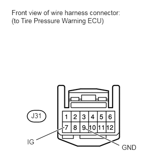
Disconnect the J31 ECU connector.


b.
U152142E02
1.771,2.667 2.469,3.01 true 1.333,2.635 0.75,2.896 true 0.24,0.177 2.51,0.625 2.271,0.448 10 false Front view of wire harness connector: (to Tire Pressure Warning ECU) 0.646,2.313 0.906,2.479 0.26,0.167 10 false J31 0.563,2.854 0.875,3.042 0.313,0.188 10 false IG 2.521,2.969 3,3.177 0.479,0.208 10 false GND

Measure the voltage and resistance according to the value(s) in the table below.

Standard Voltage:
Tester Connection Switch Condition Specified Condition
J31-7 (IG) - Body ground Ignition switch ON 11 to 14 V


Standard Resistance:
Tester Connection Condition Specified Condition
J31-9 (GND) - Body ground Always Below 1 Ω


OK

REPLACE TIRE PRESSURE WARNING ECU

NG

REPAIR OR REPLACE HARNESS OR CONNECTOR

3.CHECK HARNESS AND CONNECTOR (ECU - BATTERY)
a.

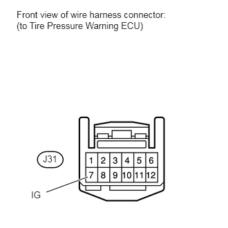
Disconnect the J31 ECU connector.


b.
U152143E02
1.323,2.667 0.698,2.896 true 0.25,0.135 2.656,0.677 2.406,0.542 10 false Front view of wire harness connector: (to Tire Pressure Warning ECU) 0.646,2.313 0.906,2.479 0.26,0.167 10 false J31 0.469,2.854 0.781,3.042 0.313,0.188 10 false IG

Measure the resistance according to the value(s) in the table below.

Standard Resistance:
Tester Connection Condition Specified Condition
J31-7 (IG) - Body ground Always 10 kΩ or higher


OK

REPLACE FUSE

NG

REPLACE FUSE AND REPAIR OR REPLACE HARNESS OR CONNECTOR