WF1AM TRANSFER 4WD CONTROL SWITCH ON-VEHICLE INSPECTION
PROCEDURE

 1.INSPECT INDICATOR LIGHT
Inspect the 4HI Indicator Light:
Start the engine.
Change the 4WD control switch from 2WD to 4H.
Check the 4HI indicator light.
- OK:
The 4HI indicator light comes on or the 4HI indicator light comes on after it is blinking.
If the result is not as specified, inspect the switch, four wheel drive control ECU and transfer shift actuator assembly.
If there is a malfunction, inspect the switch, ECU, transfer shift actuator and A.D.D. actuator. If the system is normal, there may be a malfunction in the CAN communication system or combination meter. In this case, first check the CAN communication system (See page Power Source / Network>CAN COMMUNICATION>CAN COMMUNICATION SYSTEM>PRECAUTION). Then check the combination meter (See page Vehicle Interior>METER / GAUGE / DISPLAY>METER / GAUGE SYSTEM>PROBLEM SYMPTOMS TABLE) and touch select 2-4 and high-low system (See page Drivetrain>WF1AM TRANSFER>TOUCH SELECT 2-4 AND HIGH-LOW SYSTEM>HOW TO PROCEED WITH TROUBLESHOOTING).
Inspect the 4LO Indicator Light:
Start the engine.
Move the shift lever to N.
Change the 4WD control switch from 2WD to 4H. Then change it from 4H to 4L after the 4HI indicator light illuminates (after 4H switch completion).
Check the 4LO indicator light.
- OK:
The 4LO indicator light comes on or the 4LO indicator light comes on after it is blinking.
If there is a malfunction, inspect the switch, ECU and actuator. If the system is normal, the combination meter may be malfunctioning.
84223A
2.INSPECT TRANSFER POSITION SWITCH
Remove the transfer position switch with its connector still connected (See page TF-89).
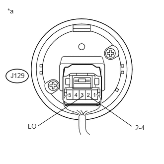
Measure the voltage according to the value(s) in the table below.
- Standard Voltage:
Tester Connection Switch Condition Specified Condition J129-2 (2-4) - Body ground Ignition switch ON
2WD positionBelow 1 V Ignition switch ON
4H positionBelow 1.5 V Ignition switch ON
4L position10.5 to 14 V J129-3 (LO) - Body ground Ignition switch ON
2WD position10.5 to 14 V Ignition switch ON
4H positionBelow 1.5 V Ignition switch ON
4L positionBelow 1 V
| *a | Component with harness connected
(Transfer Position Switch) |