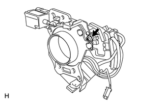
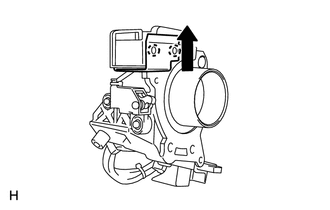
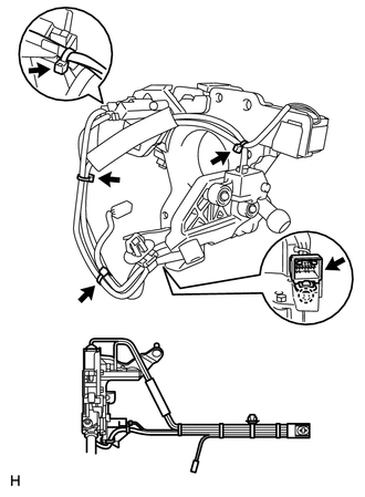
Home › Drivetrain › A760F AUTOMATIC TRANSMISSION / TRANSAXLE › SHIFT LEVER ASSEMBLY(for Column Shift Type)
RM27M0U _52 Drivetrain _049127 A760F AUTOMATIC TRANSMISSION / TRANSAXLE _0234167 SHIFT LEVER ASSEMBLY(for Column Shift Type) A

A760F AUTOMATIC TRANSMISSION / TRANSAXLE  SHIFT LEVER ASSEMBLY(for Column Shift Type)  REASSEMBLY  


PROCEDURE

Hide 84722F 1.INSTALL TRANSMISSION CONTROL SWITCH (P POSITION)
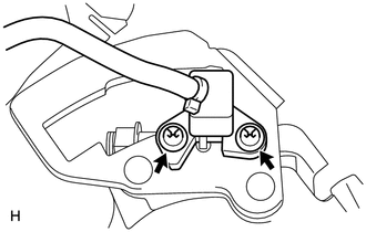
C155899

a.

Install the switch to the column shift control shift lever retainer with the 2 screws.


Hide 84722F 2.INSTALL TRANSMISSION CONTROL SWITCH (S POSITION)
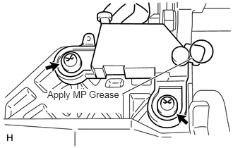
U152172E02
2.844,0.854 1.792,1.396 true 0.698,1.313 1.802,1.667 1.104,0.354 10 true Apply MP Grease

a.

Apply MP grease to the switch as shown in the illustration.


b.

Install the switch to the column shift control shift lever retainer with the 2 screws.

c.
C157300E07
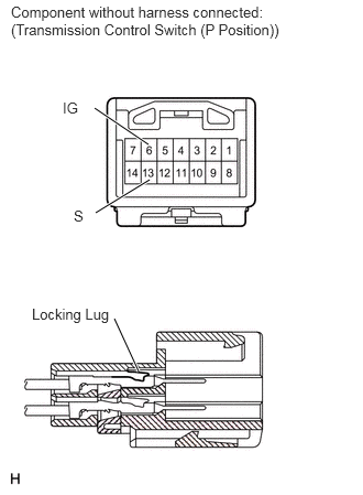
1.313,3.51 1.083,3.01 true 1.406,1.365 0.896,1.021 true 1.417,1.698 0.906,2.01 true 0.104,0.031 2.813,0.385 2.708,0.354 10 false Component without harness connected: (Transmission Control Switch (P Position)) 0.302,2.885 1.073,3.104 0.771,0.219 10 false Locking Lug 0.594,0.938 0.781,1.083 0.188,0.146 10 false IG 0.698,1.958 0.823,2.115 0.125,0.156 10 false S

Securely connect the 2 wire terminals to terminal 6 and 13 of the transmission control switch connector.


Hide 33805A 3.CONNECT NO. 1 SHIFT LOCK PLATE SUB-ASSEMBLY
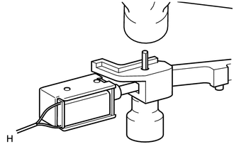
C158360

a.

Using a hammer, tap in the spring pin to connect the shift lock plate and shift lock solenoid.


Hide 85431 4.INSTALL SHIFT LOCK SOLENOID

C155894

a.

Install the shift lock solenoid with No. 1 shift lock plate sub-assembly, 2 bushes and collar to the column shift control shift lever retainer with the screw.

Torque:
1.2 N*m (12 kgf*cm, 11 in.*lbf)


b.
U152180

Attach the 2 claws to install the shift lock solenoid bracket.

c.
C157300E08
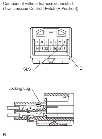
1.396,3.542 1.083,3.01 true 2.156,1.49 1.188,2.302 true 2.188,1.708 2.615,2.25 true 0.104,0.031 2.813,0.385 2.708,0.354 10 false Component without harness connected: (Transmission Control Switch (P Position)) 0.281,2.885 1.052,3.104 0.771,0.219 10 false Locking Lug 0.781,2.24 1.177,2.385 0.396,0.146 10 false SLS+ 2.677,2.208 2.813,2.375 0.135,0.167 10 false E

Securely connect the 2 wire terminals to terminal 1 and 8 of the transmission control switch connector.


Hide 33503 5.INSTALL COLUMN SHIFT SHIFT LEVER SUB-ASSEMBLY
C155892E03
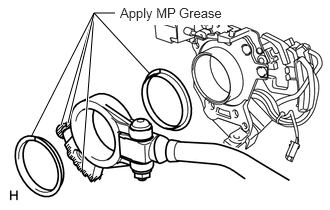
0.635,1.302 0.979,0.135 0.979,0.135 0.854,1.781 true 1.052,1.854 1.031,1.875 false 1.042,1.833 0.979,1.896 false 1.073,1.813 1.042,1.833 false 1,1.844 0.948,1.896 false 1.01,1.833 1,1.844 false 0.969,1.844 0.938,1.885 false 0.958,1.833 0.927,1.865 false 0.948,1.813 0.917,1.844 false 0.917,1.813 0.885,1.844 false 0.906,1.802 0.875,1.833 false 0.896,1.781 0.865,1.813 false 0.885,1.771 0.854,1.792 false 0.865,1.76 0.833,1.792 false 0.844,1.75 0.813,1.771 false 0.833,1.729 0.813,1.75 false 0.823,1.708 0.802,1.74 false 0.813,1.698 0.781,1.729 false 0.802,1.677 0.771,1.698 false 0.792,1.656 0.76,1.677 false 0.781,1.635 0.75,1.667 false 0.76,1.625 0.729,1.656 false 0.75,1.615 0.719,1.646 false 0.74,1.583 0.708,1.625 false 0.74,1.563 0.708,1.594 false 0.74,1.531 0.708,1.573 false 0.729,1.521 0.698,1.552 false 0.719,1.5 0.688,1.531 false 0.667,1.438 0.646,1.448 false 0.656,1.417 0.625,1.438 false 0.646,1.396 0.615,1.427 false 0.708,1.333 0.646,1.396 false 0.74,1.302 0.708,1.333 false 0.646,1.365 0.604,1.406 false 0.74,1.281 0.698,1.323 false 0.688,1.302 0.594,1.396 false 0.656,1.302 0.594,1.365 false 0.708,1.281 0.979,0.135 0.979,0.135 1.198,0.135 true 0.323,1.427 0.979,0.135 false 1.563,0.771 0.979,0.135 false 1.25,0.052 2.417,0.26 1.167,0.208 10 true Apply MP Grease

a.

Apply MP grease to the 2 lever selecting bushes as shown in the illustration.


b.

Install the 2 lever selecting bushes and shift lever to the column shift control shift lever retainer.


c.

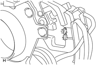
Pass the wire harness of the shift lever through the control shaft tube clamp.

d.
C155897

Attach the control shaft tube clamp to the column shift control shift lever retainer.

e.
C351976E01
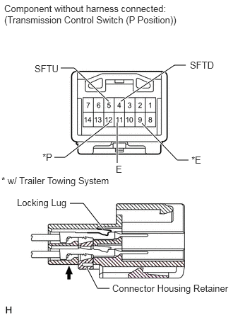
1.531,3.375 1.229,2.99 1.229,2.99 1.031,2.99 true 1.781,1.49 2.573,0.958 2.573,0.958 2.74,0.958 true 2.094,1.813 2.615,2.354 2.615,2.354 2.781,2.354 true 1.729,2.396 1.729,1.802 true 1.604,1.813 0.958,2.313 0.958,2.313 0.802,2.313 true 1.281,3.938 1.438,4.24 1.438,4.24 1.615,4.24 true 1.604,1.49 1.094,1 1.094,1 0.896,1 true 0.063,0.042 2.656,0.396 2.594,0.354 10 false Component without harness connected: (Transmission Control Switch (P Position)) 2.802,0.875 3.219,1.063 0.417,0.188 10 false SFTD 0.51,0.927 0.927,1.115 0.417,0.188 10 false SFTU 0.625,2.229 1.042,2.417 0.417,0.188 10 false *P 1.708,2.406 2.125,2.594 0.417,0.188 10 false E 2.823,2.271 3.24,2.458 0.417,0.188 10 false *E 0.021,2.573 1.781,2.792 1.76,0.219 10 false * w/ Trailer Towing System 0.25,2.896 1.125,3.073 0.875,0.177 10 false Locking Lug 1.656,4.156 3.427,4.344 1.771,0.188 10 false Connector Housing Retainer

w/o Trailer Towing System:

Securely connect the 3 wire terminals to terminal 4 (SFTD), 5 (SFTU) and 11 (E) of the transmission control switch connector. Then push the connector housing retainer to lock it.


f.

w/ Trailer Towing System:

Securely connect the 4 wire terminals to terminal 4 (SFTD), 5 (SFTU), 12 (P), 9 (E) and 11 (E) of the transmission control switch connector. Then push the connector housing retainer to lock it.


g.

Fix the connector housing retainer of the connector in place.


Hide 33564A 6.INSTALL COLUMN SHIFT SHIFT LOCK RELEASE LINK
C155891

a.

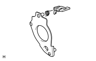
Install the spring and shift lock release link to the shift lever plate.


Hide 33502Q 7.INSTALL SHIFT LEVER PLATE SUB-ASSEMBLY
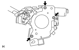
C157032

a.

Install the shift lever plate to the column shift control shift lever retainer with the 3 bolts.

Torque:
2.3 N*m (23 kgf*cm, 20 in.*lbf)


b.
C155893

Secure the harness with 4 new wire guides and the wire harness clamp as shown in the illustration.


Hide 33541G 8.INSTALL COLUMN SHIFT LEVER COMPRESSION SPRING
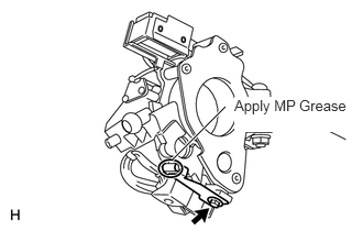
U152168E02
1.635,1.51 2.135,1.01 true 2.219,0.917 3.333,1.25 1.115,0.333 10 true Apply MP Grease

a.

Apply MP grease to the spring as shown in the illustration.


b.

Temporarily install the spring to the column shift control shift lever retainer with the bolt.
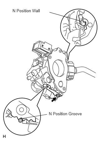

c.
U152177E01
2.712,0.705 1.65,0.405 false 0.417,0.272 1.425,0.470 1.008,0.199 10 N Position Wall 0.736,3.928 1.567,3.794 false 1.629,3.683 2.855,3.890 1.226,0.207 10 N Position Groove

With the shift lever protrusion pushed towards the N position wall of the control shift lever retainer, align the spring roller with the groove as shown in the illustration. Then tighten the bolt.

Torque:
3.8 N*m (38 kgf*cm, 33 in.*lbf)


Hide 33580 9.INSTALL COLUMN SHIFT SHIFTING BELLCRANK ASSEMBLY
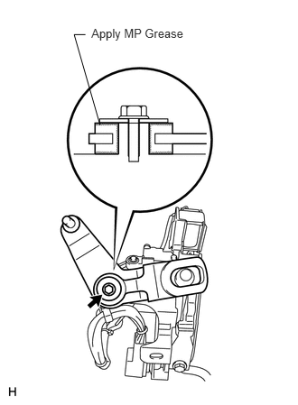
C159647E01
1.054,0.307 2.230,0.498 1.175,0.190 10 Apply MP Grease 1.154,1.444 0.855,0.399 0.855,0.399 0.985,0.399 false

a.

Apply MP grease to the shifting bellcrank as shown in the illustration.


b.

Install the shifting bellcrank with the bolt.

Torque:
5.0 N*m (51 kgf*cm, 44 in.*lbf)