Home › Drivetrain › A760E AUTOMATIC TRANSMISSION / TRANSAXLE › AUTOMATIC TRANSMISSION SYSTEM
RM27M0U _52 Drivetrain _049128 A760E AUTOMATIC TRANSMISSION / TRANSAXLE _0234192 AUTOMATIC TRANSMISSION SYSTEM J

A760E AUTOMATIC TRANSMISSION / TRANSAXLE  AUTOMATIC TRANSMISSION SYSTEM  Transmission Control Switch Circuit  


DESCRIPTION

After moving the shift lever to S, it is possible to switch the shift range between "1" (S1 range) and "6" (S6 range) using the transmission control switch.

Shifting to "+" once raises the shift range by one, and shifting to "-" once lowers the shift range by one.

WIRING DIAGRAM
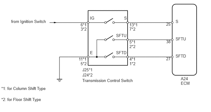
C160114E01
5.642,0.743 5.872,0.913 0.230,0.170 10 25 4.396,2.086 4.700,2.255 0.304,0.170 10 1*2 3.943,1.71 4.410,1.905 0.467,0.195 10 SFTD 4.396,1.498 4.679,1.668 0.283,0.170 10 2*2 3.943,1.122 4.410,1.317 0.467,0.195 10 SFTU 4.396,0.91 4.679,1.080 0.283,0.170 10 7*2 4.215,0.532 4.344,0.727 0.129,0.195 10 S 2.737,0.91 3.016,1.080 0.278,0.170 10 3*2 3.059,0.532 3.300,0.727 0.240,0.195 10 IG 2.737,2.086 3.034,2.255 0.297,0.170 10 5*2 3.059,1.71 3.300,1.905 0.240,0.195 10 E 5.964,0.65 6.387,0.845 0.422,0.195 10 S 5.642,1.331 5.872,1.501 0.230,0.170 10 38 5.964,1.239 6.387,1.434 0.422,0.195 10 SFTU 5.642,1.921 5.872,2.091 0.230,0.170 10 27 5.964,1.827 6.387,2.022 0.422,0.195 10 SFTD 2.797,2.292 3.219,2.487 0.422,0.195 10 J25*1 2.797,2.653 4.576,2.848 1.779,0.195 10 Transmission Control Switch 0.377,0.65 1.687,0.845 1.310,0.195 10 from Ignition Switch 6.141,2.595 6.440,2.765 0.299,0.170 10 A24 6.141,2.748 6.563,2.943 0.422,0.195 10 ECM 2.737,0.756 3.025,0.926 0.288,0.170 10 6*1 2.67,1.932 3.022,2.102 0.353,0.170 10 11*1 4.396,0.756 4.757,0.926 0.362,0.170 10 13*1 4.396,1.345 4.679,1.515 0.283,0.170 10 5*1 4.396,1.932 4.713,2.102 0.318,0.170 10 4*1 2.797,2.472 3.219,2.667 0.422,0.195 10 J24*2 0.045,2.93 1.679,3.132 1.634,0.202 10 *1: for Column Shift Type 0.045,3.303 1.679,3.505 1.634,0.202 10 *2: for Floor Shift Type

PROCEDURE

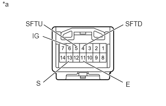
1.INSPECT TRANSMISSION CONTROL SWITCH
a.
C210665E08
1.573,0.948 0.906,0.51 true 0.896,1.698 1.427,1.26 true 1.417,0.948 0.885,0.75 true 2.542,1.698 1.719,1.26 true 1.729,0.948 2.552,0.51 true 0.052,0 0.365,0.198 0.313,0.198 10 false *a 0.531,0.406 0.979,0.604 0.448,0.198 10 false SFTU 0.75,1.635 0.938,1.833 0.188,0.198 10 false S 0.667,0.656 0.906,0.854 0.24,0.198 10 false IG 2.594,0.406 3.042,0.604 0.448,0.198 10 false SFTD 2.604,1.656 3.052,1.854 0.448,0.198 10 false E

for Column Shift Type:

i.

Disconnect the J25 transmission control switch connector.


ii.

Measure the resistance according to the value(s) in the table below.

Standard Resistance:
Tester Connection Condition Specified Condition
6 (IG) - 13 (S) Shift lever in S, "+" or "-" Below 1 Ω
5 (SFTU) - 11 (E) Shift lever held in "+"
(Up-shift)
Below 1 Ω
4 (SFTD) - 11 (E) Shift lever held in "-"
(Down-shift)
Below 1 Ω
6 (IG) - 13 (S) Shift lever not in S, "+" or "-" 10 kΩ or higher
5 (SFTU) - 11 (E) Shift lever in S 10 kΩ or higher
4 (SFTD) - 11 (E) Shift lever in S 10 kΩ or higher


Text in Illustration
*a Component without harness connected
(Transmission Control Switch)


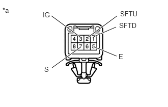
b.
C203344E34
1.802,0.76 2.396,0.323 true 1.917,0.75 2.375,0.552 true 1.646,0.76 1.052,0.323 true 1.063,1.385 1.656,0.958 true 2.385,1.146 1.927,0.958 true 0.052,0.125 0.365,0.323 0.313,0.198 10 false *a 0.875,0.219 1.188,0.417 0.313,0.198 10 false IG 0.906,1.333 1.094,1.531 0.188,0.198 10 false S 2.458,0.198 2.885,0.396 0.427,0.198 10 false SFTU 2.438,0.438 2.865,0.635 0.427,0.198 10 false SFTD 2.427,1.073 2.854,1.271 0.427,0.198 10 false E

for Floor Shift Type:

i.

Disconnect the J24 transmission control switch connector.


ii.

Measure the resistance according to the value(s) in the table below.

Standard Resistance:
Tester Connection Condition Specified Condition
3 (IG) - 7 (S) Shift lever in S, "+" or "-" Below 1 Ω
2 (SFTU) - 5 (E) Shift lever held in "+"
(Up-shift)
Below 1 Ω
1 (SFTD) - 5 (E) Shift lever held in "-"
(Down-shift)
Below 1 Ω
3 (IG) - 7 (S) Shift lever not in S, "+" or "-" 10 kΩ or higher
2 (SFTU) - 5 (E) Shift lever in S 10 kΩ or higher
1 (SFTD) - 5 (E) Shift lever in S 10 kΩ or higher


Text in Illustration
*a Component without harness connected
(Transmission Control Switch)

Result
Result Proceed to
OK A
NG (for Column Shift Type) B
NG (for Floor Shift Type) C


A

2.CHECK HARNESS AND CONNECTOR (TRANSMISSION CONTROL SWITCH - BATTERY, BODY GROUND)

B

REPLACE TRANSMISSION CONTROL SWITCH (COLUMN SHIFT SHIFT LEVER SUB-ASSEMBLY)

C

REPLACE TRANSMISSION CONTROL SWITCH (TRANSMISSION FLOOR SHIFT ASSEMBLY)

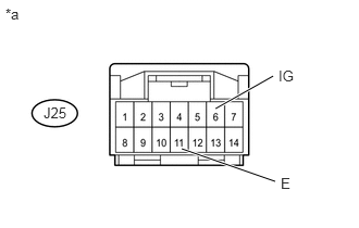
2.CHECK HARNESS AND CONNECTOR (TRANSMISSION CONTROL SWITCH - BATTERY, BODY GROUND)
a.
U152445E02
2.063,1.042 2.615,0.729 true 2.635,1.74 1.74,1.427 true 0.052,0.052 0.365,0.25 0.313,0.198 10 false *a 2.667,0.646 2.979,0.844 0.313,0.198 10 false IG 0.417,1 0.792,1.229 0.375,0.229 10 false J25 2.688,1.677 3,1.875 0.313,0.198 10 false E

for Column Shift Type:

i.

Disconnect the J25 transmission control switch connector.


ii.

Measure the voltage according to the value(s) in the table below.

Standard Voltage:
Tester Connection Switch Condition Specified Condition
J25-6 (IG) - Body ground Ignition switch ON 11 to 14 V
J25-6 (IG) - Body ground Ignition switch off Below 1 V


iii.

Measure the resistance according to the value(s) in the table below.

Standard Resistance:
Tester Connection Condition Specified Condition
J25-11 (E) - Body ground Always Below 1 Ω


Text in Illustration
*a Front view of wire harness connector
(to Transmission Control Switch)


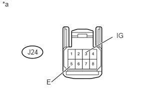
b.
U152408E02
1.802,1.083 2.344,0.771 true 1.073,1.708 1.458,1.385 true 0.052,0 0.365,0.198 0.313,0.198 10 false *a 2.427,0.656 2.74,0.854 0.313,0.198 10 false IG 0.573,1 0.948,1.229 0.375,0.229 10 false J24 0.969,1.625 1.281,1.823 0.313,0.198 10 false E

for Floor Shift Type:

i.

Disconnect the J24 transmission control switch connector.


ii.

Measure the voltage according to the value(s) in the table below.

Standard Voltage:
Tester Connection Switch Condition Specified Condition
J24-3 (IG) - Body ground Ignition switch ON 11 to 14 V
J24-3 (IG) - Body ground Ignition switch off Below 1 V


iii.

Measure the resistance according to the value(s) in the table below.

Standard Resistance:
Tester Connection Condition Specified Condition
J24-5 (E) - Body ground Always Below 1 Ω


Text in Illustration
*a Front view of wire harness connector
(to Transmission Control Switch)


OK

3.CHECK HARNESS AND CONNECTOR (TRANSMISSION CONTROL SWITCH - ECM)

NG

REPAIR OR REPLACE HARNESS OR CONNECTOR

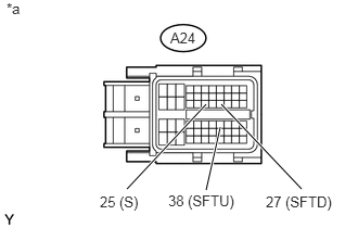
3.CHECK HARNESS AND CONNECTOR (TRANSMISSION CONTROL SWITCH - ECM)
a.
U152405E02
1.219,1.813 1.979,1 true 2.896,1.813 2.125,1 true 1.979,1.823 2.115,1.219 true 0.063,0 0.375,0.198 0.313,0.198 10 false *a 1.635,0.281 2.01,0.51 0.375,0.229 10 false A24 0.958,1.854 1.406,2.052 0.448,0.198 10 false 25 (S) 2.552,1.854 3.25,2.052 0.698,0.198 10 false 27 (SFTD) 1.615,1.844 2.344,2.042 0.729,0.198 10 false 38 (SFTU)

Disconnect the A24 ECM connector.


b.

Measure the voltage according to the value(s) in the table below.

Standard Voltage:
Tester Connection Condition Specified Condition
A24-25 (S) - Body ground
·

Ignition switch ON

·

Shift lever in S, "+" or "-"


11 to 14 V
A24-25 (S) - Body ground
·

Ignition switch ON

·

Shift lever not in S, "+" or "-"


Below 1 V


c.

Turn the ignition switch off.


d.

Measure the resistance according to the value(s) in the table below.

Standard Resistance:
Tester Connection Condition Specified Condition
A24-38 (SFTU) - Body ground Shift lever held in "+"
(Up-shift)
Below 1 Ω
A24-27 (SFTD) - Body ground Shift lever held in "-"
(Down-shift)
Below 1 Ω
A24-38 (SFTU) - Body ground Shift lever in S 10 kΩ or higher
A24-27 (SFTD) - Body ground Shift lever in S 10 kΩ or higher


Text in Illustration
*a Front view of wire harness connector
(to ECM)


OK

PROCEED TO NEXT SUSPECTED AREA SHOWN IN PROBLEM SYMPTOMS TABLE

NG

REPAIR OR REPLACE HARNESS OR CONNECTOR