RM27M0U
_55
Steering
_049129
STEERING COLUMN
_0234195
POWER TILT AND POWER TELESCOPIC STEERING COLUMN SYSTEM
C
STEERING COLUMN POWER TILT AND POWER TELESCOPIC STEERING COLUMN SYSTEM B2620 ECU Power Source Circuit Malfunction
DESCRIPTION
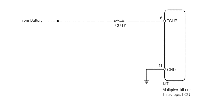
The ECU power source circuit supplies positive voltage to the multiplex tilt and telescopic ECU.
| DTC Code | Detection Condition | Trouble Area |
|---|---|---|
| B2620 | While the auto away/return function, driving position memory function or manual control is in operation, the ECU power supply voltage remains at 10 V or less for 10 sec. or more after a voltage of 8 V or less is detected. | ·
Battery ·
Harness or connector ·
Multiplex tilt and telescopic ECU |
WIRING DIAGRAM
3.917,0.802 4.552,1.021
0.635,0.219
10
false
ECU-B1
0.74,0.625 1.75,0.927
1.01,0.302
10
false
from Battery
5.792,0.646 6.271,0.906
0.479,0.26
10
false
ECUB
5.813,2.354 6.271,2.583
0.458,0.229
10
false
GND
5.552,0.521 5.74,0.708
0.188,0.188
10
false
9
5.51,2.208 5.76,2.385
0.25,0.177
10
false
11
5.646,2.854 5.969,3.01
0.323,0.156
10
false
J47
5.656,3.052 6.74,3.49
1.083,0.438
10
false
Multiplex Tilt and Telescopic ECU
PROCEDURE
1.INSPECT FUSE (ECU-B1)
a.
Remove the ECU-B1 fuse from the engine room junction block.
b.
Measure the resistance according to the value(s) in the table below.
- Standard Resistance:
Tester Connection Condition Specified Condition ECU-B1 fuse Always Below 1 Ω
OK
2.CHECK HARNESS AND CONNECTOR (MULTIPLEX TILT AND TELESCOPIC ECU - BATTERY)
NG
REPLACE FUSE
2.CHECK HARNESS AND CONNECTOR (MULTIPLEX TILT AND TELESCOPIC ECU - BATTERY)
a.
1.885,1.313 2.198,1.531
0.313,0.219
2.375,2.708 2.688,3.063
false
0.115,0.104 2.458,0.49
2.344,0.385
10
false
Rear view of wire harness connector:(to Multiplex Tilt and Telescopic ECU)
1.927,1.344 2.25,1.531
0.323,0.188
10
false
J47
2.521,3.094 3.135,3.292
0.615,0.198
10
false
ECUB
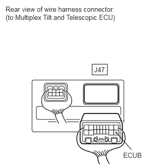
Disconnect the J47 multiplex tilt and telescopic ECU connector.
b.
Measure the voltage according to the value(s) in the table below.
- Standard Voltage:
Tester Connection Condition Specified Condition J47-9 (ECUB) - Body ground Always 11 to 14 V
OK
3.CHECK HARNESS AND CONNECTOR (MULTIPLEX TILT AND TELESCOPIC ECU - BODY GROUND)
NG
REPAIR OR REPLACE HARNESS OR CONNECTOR
3.CHECK HARNESS AND CONNECTOR (MULTIPLEX TILT AND TELESCOPIC ECU - BODY GROUND)
a.
1.927,1.281 2.281,1.5
0.354,0.219
1.365,3.021 1.844,2.594
false
0.094,0.104 2.438,0.49
2.344,0.385
10
false
Rear view of wire harness connector:(to Multiplex Tilt and Telescopic ECU)
1.979,1.302 2.26,1.49
0.281,0.188
10
false
J47
1.198,3.031 1.625,3.208
0.427,0.177
10
false
GND
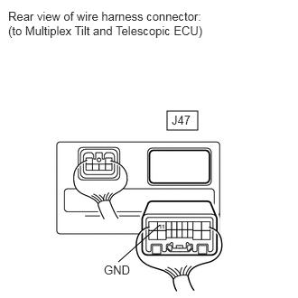
Measure the resistance according to the value(s) in the table below.
- Standard Resistance:
Tester Connection Condition Specified Condition J47-11 (GND) - Body ground Always Below 1 Ω
OK
REPLACE MULTIPLEX TILT AND TELESCOPIC ECU
NG
REPAIR OR REPLACE HARNESS OR CONNECTOR