SUSPENSION FRONT UPPER SUSPENSION ARM INSTALLATION
CAUTION / NOTICE / HINT
- HINT:
- ·
Use the same procedures for the RH side and LH side.
·The procedures listed below are for the LH side.
·A bolt without a torque specification is shown in the standard bolt chart (see page General>SPECIFICATIONS>STANDARD BOLT>SPECIFIED TORQUE FOR STANDARD BOLTS).
PROCEDURE

 48630
1.TEMPORARILY INSTALL FRONT SUSPENSION UPPER ARM ASSEMBLY LH
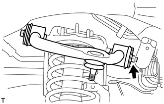
Temporarily install the suspension upper arm with the 2 washers, bolt and nut.
- HINT:
-
After stabilizing the suspension, tighten the nut.
53739A
2.INSTALL FRONT FENDER APRON SEAL REAR LH
Install the apron seal with the 5 clips.
53737B
3.INSTALL FRONT FENDER APRON SEAL LH
Install the apron seal with the 6 clips.
43212
4.CONNECT STEERING KNUCKLE LH
Connect the steering knuckle to the suspension upper arm.
Install the nut and a new cotter pin.
- Torque:
- 110 N*m (1122 kgf*cm, 81 ft.*lbf)
- NOTICE:
-
If the holes for the cotter pin are not aligned, tighten the nut further up to 60°.
89516
5.CONNECT SKID CONTROL SENSOR WIRE
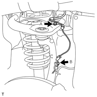
Connect the sensor wire to the steering knuckle and upper arm with the 2 bolts.
- Torque:
- for Bolt A : 13 N*m (133 kgf*cm, 10 ft.*lbf)
- for Bolt B : 29 N*m (296 kgf*cm, 21 ft.*lbf)
6.TEMPORARILY INSTALL FRONT SHOCK ABSORBER WITH COIL SPRING LH
7.STABILIZE SUSPENSION
48630
8.TIGHTEN FRONT SUSPENSION UPPER ARM ASSEMBLY LH
Tighten the nut.
- Torque:
- 235 N*m (2396 kgf*cm, 173 ft.*lbf)
9.TIGHTEN FRONT SHOCK ABSORBER WITH COIL SPRING
10.INSPECT AND ADJUST FRONT WHEEL ALIGNMENT
Inspect and adjust the front wheel alignment (see page Suspension>SUSPENSION>FRONT WHEEL ALIGNMENT>ADJUSTMENT).
11.INSTALL FRONT WHEEL
- Torque:
- for Aluminum Wheel : 131 N*m (1336 kgf*cm, 97 ft.*lbf)
- for Steel Wheel : 209 N*m (2131 kgf*cm, 154 ft.*lbf)