Home › Vehicle Interior › AIR CONDITIONING › AIR CONDITIONING SYSTEM(for Manual Air Conditioning System)
RM27M0U _58 Vehicle Interior _049154 AIR CONDITIONING _0234411 AIR CONDITIONING SYSTEM(for Manual Air Conditioning System) J

AIR CONDITIONING  AIR CONDITIONING SYSTEM(for Manual Air Conditioning System)  Blower Motor Circuit  


DESCRIPTION

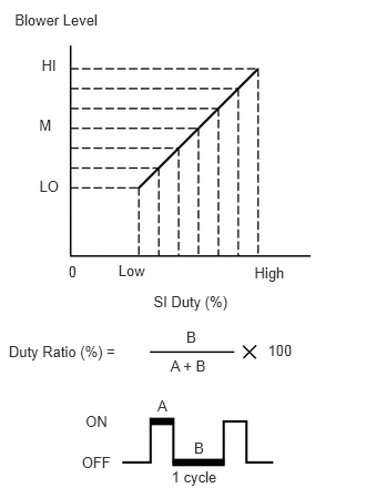
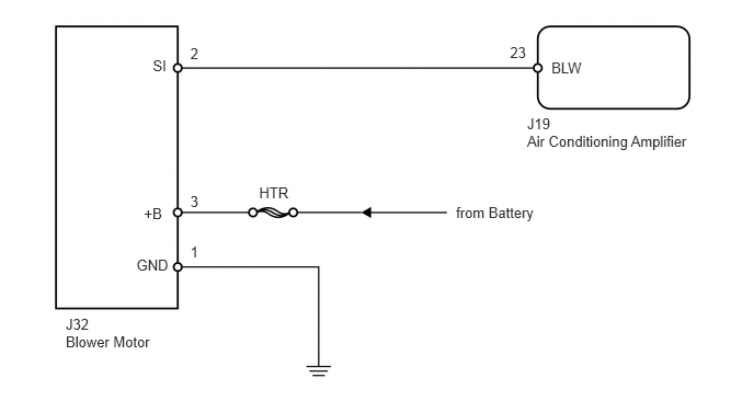
The blower motor is operated by signals from the air conditioning amplifier. Blower motor speed signals are transmitted by changes in the duty ratio.

Duty Ratio:
E132503E03
0.139,0.108 1.063,0.281 0.924,0.173 10 Blower Level 0.391,0.53 0.649,0.732 0.258,0.202 10 HI 0.368,1.098 0.640,1.305 0.272,0.207 10 M 0.37,1.671 0.643,1.893 0.273,0.222 10 LO 0.643,2.469 0.799,2.680 0.156,0.211 10 0 1.112,2.461 1.427,2.607 0.315,0.147 10 Low 2.39,2.48 2.767,2.673 0.377,0.193 10 High 1.442,2.75 2.200,2.953 0.758,0.203 10 SI Duty (%) 0.082,3.224 1.130,3.417 1.048,0.193 10 Duty Ratio (%) = 1.601,3.35 2.016,3.515 0.415,0.165 10 A + B 1.75,3.086 1.942,3.279 0.193,0.193 10 B 1.479,3.733 1.672,3.926 0.193,0.193 10 A 1.823,4.129 2.016,4.322 0.193,0.193 10 B 2.516,3.21 2.822,3.378 0.306,0.169 10 100 0.803,3.871 1.088,4.061 0.286,0.191 10 ON 0.768,4.26 1.146,4.444 0.378,0.184 10 OFF 1.611,4.392 2.128,4.533 0.517,0.141 10 1 cycle

The duty ratio is the ratio of the blower motor OFF time (B) to the total of the blower motor ON and OFF time (A + B).

The blower motor controller controls the blower motor speed.

WIRING DIAGRAM
E146215E02
5.01,1.092 6.662,1.250 1.653,0.157 10 J19 5.241,0.56 5.616,0.717 0.375,0.157 10 BLW 4.848,0.413 5.064,0.570 0.215,0.157 10 23 5.01,1.26 6.662,1.418 1.653,0.157 10 Air Conditioning Amplifier 4.334,1.936 5.198,2.094 0.864,0.157 10 from Battery 2.463,1.747 2.848,1.905 0.385,0.157 10 HTR 1.452,0.547 1.730,0.704 0.278,0.157 10 SI 1.368,1.948 1.646,2.105 0.278,0.157 10 +B 1.297,2.433 1.682,2.591 0.385,0.157 10 GND 1.809,0.43 2.195,0.588 0.385,0.157 10 2 1.809,1.831 2.195,1.989 0.385,0.157 10 3 1.809,2.317 2.195,2.474 0.385,0.157 10 1 0.625,2.998 1.618,3.155 0.993,0.157 10 J32 0.625,3.166 1.618,3.323 0.993,0.157 10 Blower Motor

PROCEDURE

1.INSPECT FUSE (HTR)
a.

Remove the HTR H-fuse from the engine room relay block, junction block.


b.

Measure the resistance according to the value(s) in the table below.

Standard resistance:
Tester Connection Condition Specified Condition
HTR H-fuse Always Below 1 Ω


OK

2.CHECK HARNESS AND CONNECTOR (BLOWER MOTOR - BATTERY AND BODY GROUND)

NG

REPLACE FUSE

2.CHECK HARNESS AND CONNECTOR (BLOWER MOTOR - BATTERY AND BODY GROUND)
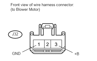
U152747E02
2.083,1.646 2.573,1.885 false 1.281,1.625 0.792,1.865 false 0.375,0.083 2.688,0.49 2.313,0.406 10 false Front view of wire harness connector: (to Blower Motor) 0.427,1.135 0.688,1.323 0.26,0.188 10 false J32 0.427,1.833 0.76,2.01 0.333,0.177 10 false GND 2.635,1.844 2.875,2.052 0.24,0.208 10 false +B

a.

Disconnect the J32 blower motor connector.


b.

Measure the resistance and voltage according to the value(s) in the table below.

Standard resistance:
Tester Connection Condition Specified Condition
J32-1 (GND) - Body ground Always Below 1 Ω


Standard voltage:
Tester Connection Condition Specified Condition
J32-3 (+B) - Body ground Always 11 to 14 V


OK

3.CHECK HARNESS AND CONNECTOR (AIR CONDITIONING AMPLIFIER - BLOWER MOTOR)

NG

REPAIR OR REPLACE HARNESS OR CONNECTOR

3.CHECK HARNESS AND CONNECTOR (AIR CONDITIONING AMPLIFIER - BLOWER MOTOR)
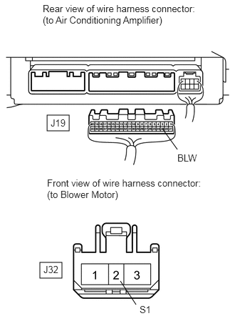
E344843E02
0.688,1.677 1.01,1.906 0.323,0.229 0.583,3.823 0.906,4.052 0.323,0.229 2.594,2.177 2.375,1.875 false 1.99,4.438 1.76,4.094 false 0.625,0.042 2.854,0.417 2.229,0.375 10 false Rear view of wire harness connector: (to Air Conditioning Amplifier) 0.635,3.844 0.906,4.052 0.271,0.208 10 false J32 2.594,2.219 2.969,2.427 0.375,0.208 10 false BLW 0.688,2.583 2.979,2.948 2.292,0.365 10 false Front view of wire harness connector: (to Blower Motor) 2.042,4.427 2.313,4.635 0.271,0.208 10 false S1 0.74,1.708 1.01,1.917 0.271,0.208 10 false J19

a.

Disconnect the J19 air conditioning amplifier connector.


b.

Disconnect the J32 blower motor connector.


c.

Measure the resistance according to the value(s) in the table below.

Standard resistance:
Tester Connection Condition Specified Condition
J19-23 (BLW) - J32-2 (SI) Always Below 1 Ω
J19-23 (BLW) or J32-2 (SI) - Body ground Always 10 kΩ or higher


OK

4.CHECK BLOWER MOTOR

NG

REPAIR OR REPLACE HARNESS OR CONNECTOR

4.CHECK BLOWER MOTOR
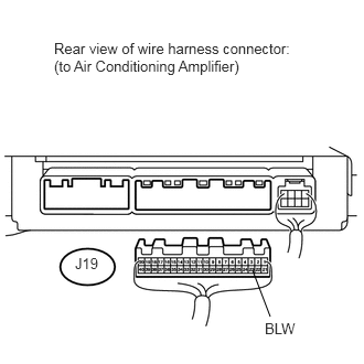
U152753E02
2.385,2.552 2.552,2.99 false 0.51,0.375 2.75,0.75 2.24,0.375 10 false Rear view of wire harness connector: (to Air Conditioning Amplifier) 0.708,2.406 0.99,2.625 0.281,0.219 10 false J19 2.5,3.021 2.906,3.24 0.406,0.219 10 false BLW

a.

Disconnect the J19 air conditioning amplifier connector.


b.

Reconnect the J32 blower motor connector.


c.

Measure the voltage according to the value(s) in the table below.

Standard voltage:
Tester Connection Switch Condition Specified Condition
J19-23 (BLW) - Body ground Ignition switch ON 4.5 to 5.5 V


OK

5.CHECK AIR CONDITIONING AMPLIFIER (BLW VOLTAGE)

NG

5.CHECK AIR CONDITIONING AMPLIFIER (BLW VOLTAGE)
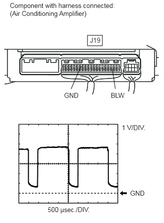
E344844E01
1.833,0.74 2.146,0.958 0.313,0.219 1.49,1.865 1.698,1.385 false 2.417,1.865 2.354,1.458 false 0.208,0.031 2.438,0.385 2.229,0.354 10 false Component with harness connected: (Air Conditioning Amplifier) 1.885,0.76 2.167,0.958 0.281,0.198 10 false J19 1.344,1.917 1.698,2.115 0.354,0.198 10 false GND 2.323,1.917 2.677,2.115 0.354,0.198 10 false BLW 2.552,2.594 3.156,2.802 0.604,0.208 10 false 1 V/DIV. 2.729,3.969 3.083,4.167 0.354,0.198 10 false GND 1,4.313 1.969,4.521 0.969,0.208 10 false 500 μsec./DIV.

a.

Remove the air conditioning amplifier with its connectors still connected (see page Vehicle Interior>AIR CONDITIONING>AIR CONDITIONING AMPLIFIER>REMOVAL).


b.

Turn the ignition switch ON.


c.

Turn the blower switch LO.


d.

Using an oscilloscope, check the waveform.

Standard:
Tester Connection Tool Setting Switch Condition Specified Condition
J19-23 (BLW) - J19-14 (GND) 1 V/DIV., 500 μsec./DIV. Ignition switch ON
Blower switch LO
Pulse generation


HINT:

Waveform varies with the blower level.


OK

PROCEED TO NEXT CIRCUIT INSPECTION SHOWN IN PROBLEM SYMPTOMS TABLE

NG

REPLACE AIR CONDITIONING AMPLIFIER