Home › Vehicle Interior › AIR CONDITIONING › AIR CONDITIONING SYSTEM(for Automatic Air Conditioning System)
RM27M0U _58 Vehicle Interior _049154 AIR CONDITIONING _0234412 AIR CONDITIONING SYSTEM(for Automatic Air Conditioning System) C

AIR CONDITIONING  AIR CONDITIONING SYSTEM(for Automatic Air Conditioning System)  B1422/22  Compressor Lock Sensor Circuit  


DESCRIPTION

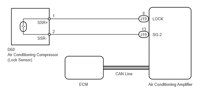
The ECM sends an engine speed signal to the air conditioning amplifier via the CAN communication system.

The air conditioning amplifier reads the difference between compressor speed and engine speed. When the difference becomes too large, the air conditioning amplifier determines that the compressor locks, and turns the magnetic clutch off.

DTC Code DTC Detection Condition Trouble Area
B1422/22 Open or short in compressor lock sensor circuit
·

Air conditioning compressor (lock sensor)

·

Compressor drive belt

·

Harness or connector between air conditioning compressor (lock sensor) and air conditioning amplifier

·

Air conditioning amplifier

·

CAN communication system


WIRING DIAGRAM

E146212E01
2.711,2.815 3.108,2.952 0.397,0.137 10 ECM 3.96,2.451 4.616,2.588 0.656,0.137 10 CAN Line 5.087,2.815 6.827,2.952 1.739,0.137 10 Air Conditioning Amplifier 0.259,1.619 0.695,1.757 0.437,0.137 10 D60 1.8,0.461 1.947,0.599 0.147,0.137 10 1 1.8,1.003 1.947,1.140 0.147,0.137 10 2 5.23,0.56 5.685,0.698 0.455,0.137 10 LOCK 5.23,1.102 5.685,1.239 0.455,0.137 10 SG-2 4.81,0.56 5.084,0.698 0.274,0.137 10 J19 4.81,1.102 5.084,1.239 0.274,0.137 10 J19 4.887,0.374 5.085,0.511 0.198,0.137 10 8 4.855,0.919 5.053,1.057 0.198,0.137 10 13 1.282,0.685 1.719,0.823 0.437,0.137 10 SSR+ 1.282,1.227 1.719,1.365 0.437,0.137 10 SSR- 0.259,1.797 2.167,1.934 1.909,0.137 10 Air Conditioning Compressor 0.259,1.974 1.998,2.112 1.739,0.137 10 (Lock Sensor)

PROCEDURE

1.CHECK FOR DTC (CAN COMMUNICATION SYSTEM)
a.

Use the Techstream to check if the CAN communication system is functioning normally.

Result
Result Proceed to
CAN DTC is not output A
CAN DTC is output B


A

2.CHECK AIR CONDITIONING AMPLIFIER

B

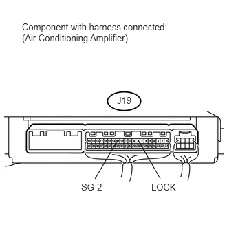
2.CHECK AIR CONDITIONING AMPLIFIER
U152744E02
1.781,2.125 1.438,2.708 false 2.094,2.125 2.427,2.708 false 0.333,0.323 2.573,0.688 2.24,0.365 10 false Component with harness connected: (Air Conditioning Amplifier) 1.771,1.438 2.031,1.625 0.26,0.188 10 false J19 2.292,2.75 2.688,2.927 0.396,0.177 10 false LOCK 1.229,2.75 1.625,2.927 0.396,0.177 10 false SG-2

a.

Remove the air conditioning amplifier with the connectors still connected (see page Vehicle Interior>AIR CONDITIONING>AIR CONDITIONING AMPLIFIER>REMOVAL).
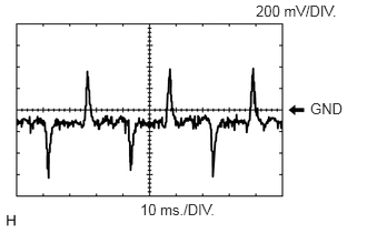

E147483E05
2.906,0.938 3.292,1.146 0.385,0.208 10 false GND 2.396,0.021 3.219,0.198 0.823,0.177 10 false 200 mV/DIV. 1.313,1.885 2.115,2.094 0.802,0.208 10 false 10 ms./DIV.

b.

Using an oscilloscope, check the waveform.

Standard:
Tester Connection Tool Setting Condition Specified Condition
J19-8 (LOCK) - J19-13 (SG-2) 200 mV/DIV., 10 ms./DIV. Engine is running
A/C switch ON
Blower switch LO
Pulse generation


Result
Result Proceed to
NG A
OK (Checking from the PROBLEM SYMPTOMS TABLE) B
OK (Checking from the DTC) C


A

3.INSPECT AIR CONDITIONING COMPRESSOR (LOCK SENSOR)

B

C

REPLACE AIR CONDITIONING AMPLIFIER

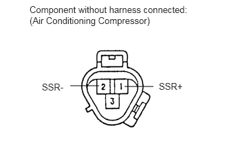
3.INSPECT AIR CONDITIONING COMPRESSOR (LOCK SENSOR)
E344838E01
1.885,1.313 2.323,1.313 false 1.063,1.302 1.5,1.302 false 0.448,0.063 2.906,0.448 2.458,0.385 10 false Component without harness connected: (Air Conditioning Compressor) 2.406,1.229 2.854,1.448 0.448,0.219 10 false SSR+ 0.635,1.24 1.083,1.458 0.448,0.219 10 false SSR-

a.

Disconnect the connector from the air conditioning compressor.


b.

Measure the resistance according to the value(s) in the table below.

Standard resistance:
Tester Connection Condition Specified Condition
1 (SSR+) - 2 (SSR-) 20°C (68°F) 65 to 125 Ω


OK

4.CHECK HARNESS AND CONNECTOR (AIR CONDITIONING AMPLIFIER - AIR CONDITIONING COMPRESSOR)

NG

REPLACE AIR CONDITIONING COMPRESSOR (LOCK SENSOR)

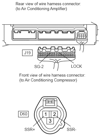
4.CHECK HARNESS AND CONNECTOR (AIR CONDITIONING AMPLIFIER - AIR CONDITIONING COMPRESSOR)
a.
E344839E01
0.76,1.698 1.104,1.906 0.344,0.208 0.625,3.792 0.969,4 0.344,0.208 2.01,1.802 2.51,2.156 false 1.719,1.802 1.344,2.156 false 1.5,3.958 1.125,4.313 false 1.906,3.958 2.406,4.313 false 0.531,0.042 2.771,0.438 2.24,0.396 10 false Rear view of wire harness connector: (to Air Conditioning Amplifier) 0.656,2.479 2.938,2.875 2.281,0.396 10 false Front view of wire harness connector: (to Air Conditioning Compressor) 1.167,2.188 1.594,2.427 0.427,0.24 10 false SG-2 2.417,2.177 2.844,2.417 0.427,0.24 10 false LOCK 0.823,1.719 1.156,1.906 0.333,0.188 10 false J19 0.677,3.802 1.01,3.99 0.333,0.188 10 false D60 0.833,4.333 1.26,4.573 0.427,0.24 10 false SSR+ 2.271,4.333 2.698,4.573 0.427,0.24 10 false SSR-

Disconnect the J19 air conditioning amplifier connector.


b.

Disconnect the D60 air conditioning compressor connector.


c.

Measure the resistance according to the value(s) in the table below.

Standard resistance:
Tester Connection Condition Specified Condition
J19-8 (LOCK) - D60-1 (SSR+) Always Below 1 Ω
J19-13 (SG-2) - D60-2 (SSR-)
J19-8 (LOCK) or D60-1 (SSR+) - Body ground Always 10 kΩ or higher
J19-13 (SG-2) or D60-2 (SSR-) - Body ground


OK

REPLACE AIR CONDITIONING AMPLIFIER

NG

REPAIR OR REPLACE HARNESS OR CONNECTOR