AIR CONDITIONING FRONT EVAPORATOR TEMPERATURE SENSOR INSTALLATION
PROCEDURE

 88625
1.INSTALL NO. 1 COOLER THERMISTOR
- NOTICE:
-
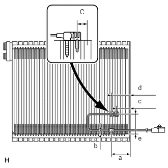 2.822,1.709 2.960,1.874 0.137,0.165 10 d 2.822,1.984 2.960,2.149 0.137,0.165 10 c 2.822,2.737 2.960,2.903 0.137,0.165 10 e 2.421,3.138 2.559,3.304 0.137,0.165 10 a 1.92,2.894 2.058,3.059 0.137,0.165 10 b 1.629,0.159 1.804,0.357 0.175,0.198 10 C
-
If reusing the evaporator, do not insert the No. 1 cooler thermistor into a location where the No. 1 cooler thermistor was previously inserted. Insert the No. 1 cooler thermistor within range C shown in the illustration.
Install the No. 1 cooler thermistor to the No. 1 cooler evaporator sub-assembly as shown in the illustration.
| Area | Standard Dimension |
|---|---|
| a | 48 mm (1.89 in.) |
| b | 8.7 to 9.0 mm (0.343 to 0.354 in.) |
| c | 34.3 mm (1.35 in.) |
| d | 47.7 mm (1.88 in.) |
| e | 48 to 52 mm (1.89 to 2.04 in.) |
88501
2.INSTALL NO. 1 COOLER EVAPORATOR SUB-ASSEMBLY
Install the No. 1 cooler evaporator sub-assembly to the blower assembly.
87130D
3.INSTALL BLOWER ASSEMBLY
Attach the 3 claws to install the blower assembly.
Install the 6 screws.
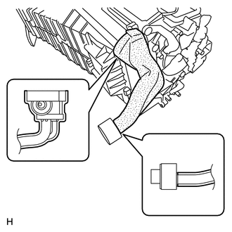
Install a new No. 2 cooler unit packing and a new No. 1 cooler unit packing.
Attach the 3 claws to install the heater clamp.
88650E
4.INSTALL AIR CONDITIONING AMPLIFIER ASSEMBLY
87201F
5.INSTALL NO. 3 AIR DUCT SUB-ASSEMBLY
6.INSTALL AIR CONDITIONING UNIT