AIR CONDITIONING AIR CONDITIONING UNIT INSTALLATION
PROCEDURE

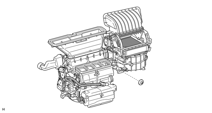
 1.INSTALL AIR CONDITIONING UNIT
Install the air conditioning unit with the nut.
- Torque:
- 5.4 N*m (55 kgf*cm, 48 in.*lbf)
87212
2.INSTALL REAR NO. 1 AIR DUCT (except Regular Cab)
Attach the 7 claws to install the rear No. 1 air duct.
87214D
3.INSTALL REAR NO. 3 AIR DUCT (except Regular Cab)
Attach the 7 claws to install the rear No. 3 air duct.
55330B
4.INSTALL INSTRUMENT PANEL REINFORCEMENT ASSEMBLY
Install the instrument panel reinforcement assembly.
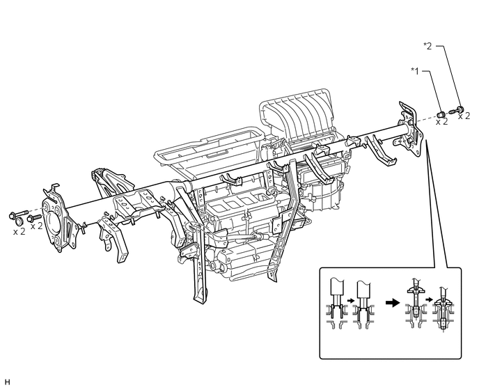
| *1 | ''TORX'' Bolt | *2 | Collar |
Temporarily install the instrument panel reinforcement assembly.
for Passenger Side:
Using a 12 mm hexagon wrench, install the 2 collars.
for Passenger Side:
Using a T40 "TORX" socket, install the 2 "TORX" bolts.
- Torque:
- 18 N*m (184 kgf*cm, 13 ft.*lbf)
for Driver Side:
Install the 3 bolts and 2 caps.
Attach the clamps and connectors to connect the wire harness.
Install the 11 bolts and 4 nuts.
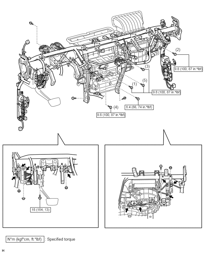
- HINT:
-
Tighten the bolt in the order shown in the illustration to install the instrument panel reinforcement assembly to the air conditioning unit.
55301
5.INSTALL INSTRUMENT PANEL SUB-ASSEMBLY
for Column Shift Type: (See page Vehicle Interior>INTERIOR PANEL>INSTRUMENT PANEL SAFETY PAD(for Column Shift Type)>INSTALLATION)
for Floor Shift Type: (See page Vehicle Interior>INTERIOR PANEL>INSTRUMENT PANEL SAFETY PAD(for Floor Shift Type)>INSTALLATION)
45250
6.INSTALL STEERING COLUMN ASSEMBLY
7.INSTALL FRONT WIPER MOTOR AND BRACKET
87246A
8.CONNECT INLET HEATER WATER HOSE AND OUTLET HEATER WATER HOSE
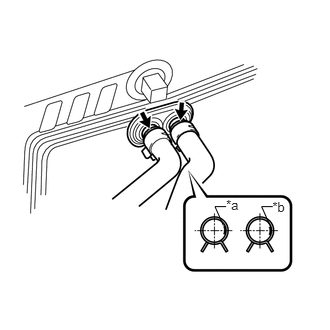
Connect the inlet heater water hose and outlet heater water hose with the paint mark facing right and attach the clip shown in the illustration.
| *a | Paint Mark (Yellow) |
| *b | Paint Mark (White) |
88707
9.CONNECT SUCTION PIPE SUB-ASSEMBLY AND AIR CONDITIONER TUBE ASSEMBLY
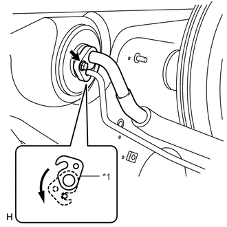
Remove the attached vinyl tape from the tubes.
Sufficiently apply compressor oil to 2 new O-rings and the fitting surface of the suction pipe sub-assembly and air conditioner tube assembly.
- Compressor oil:
ND-OIL 8 or equivalent
Install the 2 O-rings to the suction pipe sub-assembly and air conditioner tube assembly.
Connect the suction pipe sub-assembly and air conditioner tube assembly.
- HINT:
-
After the connection, check that the claw of the piping clamp is engaged.
Attach the plate as shown in the illustration and install the bolt.
- Torque:
- 9.8 N*m (100 kgf*cm, 87 in.*lbf)
| *1 | Plate |
88892N
10.INSTALL NO. 2 COOLER COVER
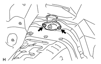
Attach the 2 claws to install the No. 2 cooler cover.
Install the 2 nuts.
- Torque:
- 5.4 N*m (55 kgf*cm, 48 in.*lbf)
11.CONNECT CABLE TO NEGATIVE BATTERY TERMINAL
- NOTICE:
-
When disconnecting the cable, some systems need to be initialized after the cable is reconnected (See page General>INTRODUCTION>REPAIR INSTRUCTION>INITIALIZATION).
12.CHECK SRS WARNING LIGHT
13.ADD ENGINE COOLANT
for 1UR-FE: (See page Engine / Hybrid System>1UR-FE COOLING>COOLANT>REPLACEMENT)
for 3UR-FE: (See page Engine / Hybrid System>3UR-FE COOLING>COOLANT>REPLACEMENT)
for 3UR-FBE: (See page Engine / Hybrid System>3UR-FBE COOLING>COOLANT>REPLACEMENT)
14.CHARGE REFRIGERANT
15.WARM UP ENGINE
16.CHECK FOR ENGINE COOLANT LEAK
17.CHECK FOR REFRIGERANT GAS LEAK