Home › Vehicle Interior › THEFT DETERRENT › THEFT DETERRENT SYSTEM
RM27M0U _58 Vehicle Interior _049155 THEFT DETERRENT _0234426 THEFT DETERRENT SYSTEM J

THEFT DETERRENT  THEFT DETERRENT SYSTEM  Security Indicator Light Circuit  


DESCRIPTION

When the theft deterrent system is in the disarmed state, the security indicator will flash continuously if the immobiliser system is set, or not illuminate if the immobiliser system is not set.

When the theft deterrent system is in the armed state, the immobiliser system is automatically set and the security indicator will flash continuously.

When the theft deterrent system is in the arming preparation state and alarm sounding state, the main body ECU causes the security indicator to be illuminated.


WIRING DIAGRAM
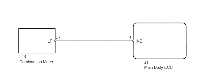
B443066E01
0.656,2 1.865,2.188 1.208,0.188 10 false Combination Meter 4.875,2.188 6.083,2.375 1.208,0.188 10 false Main Body ECU 0.656,1.823 0.979,2 0.323,0.177 10 false J28 1.604,1.302 1.833,1.469 0.229,0.167 10 false LP 1.896,1.177 2.125,1.344 0.229,0.167 10 false 37 4.365,1.177 4.521,1.354 0.156,0.177 10 false 4 4.583,1.302 4.833,1.479 0.25,0.177 10 false IND 4.875,2.021 5.198,2.198 0.323,0.177 10 false J1

PROCEDURE

1.PERFORM ACTIVE TEST USING TECHSTREAM (SECURITY INDICATOR)
a.

Operate the Techstream according to the steps on the display and select "Active Test".

Main Body
Tester Display Test Part Control Range Diagnostic Note
Security Indicator Security indicator ON/OFF -

OK:

Security indicator illuminates.


OK

PROCEED TO NEXT CIRCUIT INSPECTION SHOWN IN PROBLEM SYMPTOMS TABLE

NG

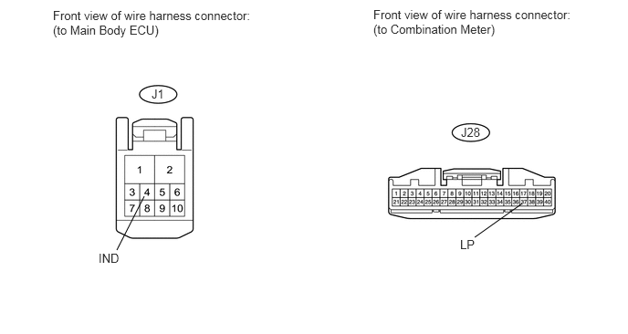
2.CHECK HARNESS AND CONNECTOR (COMBINATION METER - MAIN BODY ECU)
U152068E02
1.646,2.24 1.333,2.854 false 5.958,2.323 5.417,2.708 false 0.604,0.094 2.979,0.563 2.375,0.469 10 false Front view of wire harness connector: (to Main Body ECU) 4.26,0.083 6.667,0.604 2.406,0.521 10 false Front view of wire harness connector: (to Combination Meter) 1.125,2.865 1.385,3.042 0.26,0.177 10 false IND 5.26,1.427 5.521,1.604 0.26,0.177 10 false J28 1.729,0.99 1.896,1.167 0.167,0.177 10 false J1 5.25,2.708 5.667,2.885 0.417,0.177 10 false LP

a.

Disconnect the J1 main body ECU connector.


b.

Disconnect the J28 combination meter connector.


c.

Measure the resistance according to the value(s) in the table below.

Standard resistance:
Tester Connection Condition Specified Condition
J28-37 (LP) - J1-4 (IND) Always Below 1 Ω
J28-37 (LP) - Body ground Always 10 kΩ or higher


OK

3.REPLACE COMBINATION METER ASSEMBLY

NG

REPAIR OR REPLACE HARNESS OR CONNECTOR

3.REPLACE COMBINATION METER ASSEMBLY
a.

Temporarily replace the combination meter assembly with a new or normally functioning one (See page Vehicle Interior>METER / GAUGE / DISPLAY>COMBINATION METER>REMOVAL).


b.

Check security indicator light.

OK:

Security indicator illuminates.


OK

END (COMBINATION METER WAS DEFECTIVE)

NG

REPLACE MAIN BODY ECU