Home › Vehicle Interior › THEFT DETERRENT › THEFT DETERRENT SYSTEM
RM27M0U _58 Vehicle Interior _049155 THEFT DETERRENT _0234426 THEFT DETERRENT SYSTEM J

THEFT DETERRENT  THEFT DETERRENT SYSTEM  Glass Breakage Sensor ECU Circuit  


DESCRIPTION

When the glass breakage sensor detects the glass is broken (1st time), the sensor will set off an alarm for 20 seconds (pre-alarm). If the glass breakage sensor detects that more glass is broken (2nd time or more), the sensor will set off an alarm for 60 seconds.

WIRING DIAGRAM
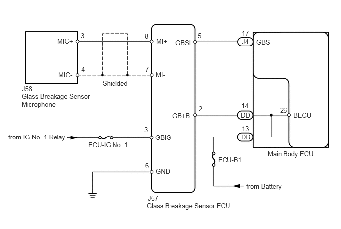
B233068E03
0.458,1.781 1.104,2.021 0.646,0.24 10 false J58 0.458,1.948 2.469,2.375 2.01,0.427 10 false Glass Breakage Sensor Microphone 1.229,1.49 1.854,1.74 0.625,0.25 10 false MIC- 1.208,0.781 1.833,1.031 0.625,0.25 10 false MIC+ 1.698,0.667 1.917,0.885 0.219,0.219 10 false 3 1.708,1.375 1.927,1.594 0.219,0.219 10 false 4 2.156,1.667 2.75,1.875 0.594,0.208 10 false Shielded 3.042,0.677 3.26,0.896 0.219,0.219 10 false 8 3.052,1.375 3.271,1.594 0.219,0.219 10 false 7 3.281,0.781 3.563,1.031 0.281,0.25 10 false MI+ 3.271,1.49 3.896,1.74 0.625,0.25 10 false MI- 4.156,0.667 4.375,0.885 0.219,0.219 10 false 5 3.688,0.813 4.063,1.063 0.375,0.25 10 false GBSI 3.625,2.354 4.25,2.604 0.625,0.25 10 false GB+B 4.177,2.208 4.396,2.427 0.219,0.219 10 false 2 5.083,0.615 5.302,0.833 0.219,0.219 10 false 17 5.073,2.146 5.292,2.365 0.219,0.219 10 false 14 5.083,2.625 5.302,2.844 0.219,0.219 10 false 13 5.083,0.792 5.5,0.979 0.417,0.188 10 false J4 5.063,2.344 5.479,2.531 0.417,0.188 10 false DD 5.073,2.802 5.49,2.99 0.417,0.188 10 false DB 5.385,0.802 6.01,1.052 0.625,0.25 10 false GBS 5.885,2.24 6.104,2.458 0.219,0.219 10 false 26 6.167,2.344 6.792,2.594 0.625,0.25 10 false BECU 0.177,2.802 1.406,3.01 1.229,0.208 10 false from IG No. 1 Relay 3.083,4.25 4.99,4.458 1.906,0.208 10 false Glass Breakage Sensor ECU 1.854,2.969 2.833,3.24 0.979,0.271 10 false ECU-IG No. 1 3.031,2.646 3.25,2.865 0.219,0.219 10 false 3 3.26,2.813 3.885,3.063 0.625,0.25 10 false GBIG 3.052,3.406 3.271,3.625 0.219,0.219 10 false 6 3.271,3.521 3.896,3.771 0.625,0.25 10 false GND 3.104,4.094 3.75,4.333 0.646,0.24 10 false J57 4.583,3.281 5.208,3.531 0.625,0.25 10 false ECU-B1 5.177,3.844 6.073,4.083 0.896,0.24 10 false from Battery 5.625,3.156 6.729,3.354 1.104,0.198 10 false Main Body ECU

PROCEDURE

1.READ VALUE USING TECHSTREAM (GLASS BREAKAGE SENSOR)
a.

Using the Techstream, read the Data List.

MAIN BODY
Tester Display Measurement Item/Range Normal Condition Diagnostic Note
Glass Break Sensor Detection Glass breakage sensor detection / ON or OFF ON: Glass breakage sensor ON
OFF: Glass breakage sensor OFF
-

OK:

When tapping on the door glass with your finger, "ON" is displayed on the Techstream screen.


OK

PROCEED TO NEXT CIRCUIT INSPECTION SHOWN IN PROBLEM SYMPTOMS TABLE

NG

2.INSPECT FUSE (ECU-IG No. 1)
a.

Remove the ECU-IG No. 1 fuse from the main body ECU.


b.

Measure the resistance according to the value(s) in the table below.

Standard resistance:
Tester Connection Condition Specified Condition
ECU-IG No. 1 fuse Always Below 1 Ω


OK

3.CHECK HARNESS AND CONNECTOR (GLASS BREAKAGE SENSOR ECU - BATTERY AND BODY GROUND)

NG

REPLACE FUSE

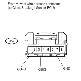
3.CHECK HARNESS AND CONNECTOR (GLASS BREAKAGE SENSOR ECU - BATTERY AND BODY GROUND)
a.
U151903E02
2.281,2.156 2.677,2.813 false 1.698,2.177 1.729,2.833 false 1.417,2.177 0.896,2.833 false 0.333,0.073 2.656,0.417 2.323,0.344 10 false Front view of wire harness connector: (to Glass Breakage Sensor ECU) 0.396,1.656 0.635,1.833 0.24,0.177 10 false J57 1.625,2.865 1.99,3.042 0.365,0.177 10 false GBIG 0.729,2.854 1.125,3.031 0.396,0.177 10 false GB+B 2.677,2.823 3,3 0.323,0.177 10 false GND

Disconnect the J57 glass breakage sensor ECU connector.


b.

Measure the voltage and resistance according to the value(s) in the table below.

Standard voltage:
Tester Connection Switch Condition Specified Condition
J57-2 (GB+B) - J57-6 (GND) Always 11 to 14 V
J57-3 (GBIG) - J57-6 (GND) Ignition switch ON 11 to 14 V
Ignition switch off Below 1 V


Standard resistance:
Tester Connection Condition Specified Condition
J57-6 (GND) - Body ground Always Below 1 Ω


OK

4.CHECK HARNESS AND CONNECTOR (MAIN BODY ECU - GLASS BREAKAGE SENSOR ECU)

NG

REPAIR OR REPLACE HARNESS OR CONNECTOR

4.CHECK HARNESS AND CONNECTOR (MAIN BODY ECU - GLASS BREAKAGE SENSOR ECU)
a.

Disconnect the J4 main body ECU connector.
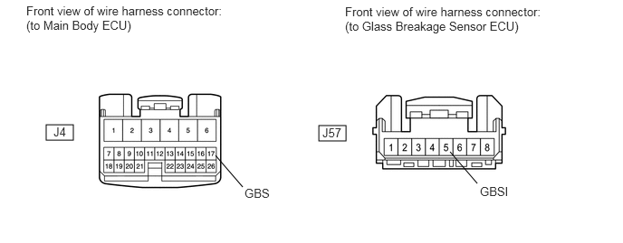
B443063E01
3.667,1.448 3.979,1.625 0.313,0.177 0.531,1.438 0.844,1.615 0.313,0.177 5.49,2.115 5.177,1.75 false 2.792,2.156 2.479,1.792 false 0.302,0.042 2.573,0.438 2.271,0.396 10 false Front view of wire harness connector: (to Main Body ECU) 3.969,0.052 6.24,0.448 2.271,0.396 10 false Front view of wire harness connector: (to Glass Breakage Sensor ECU) 0.615,1.438 0.958,1.635 0.344,0.198 10 false J4 3.708,1.448 4.052,1.646 0.344,0.198 10 false J57 5.521,2.125 5.958,2.302 0.438,0.177 10 false GBSI 2.813,2.146 3.25,2.323 0.438,0.177 10 false GBS


b.

Disconnect the J57 glass breakage sensor ECU connector.

c.

Measure the resistance according to the value(s) in the table below.

Standard resistance:
Tester Connection Condition Specified Condition
J4-17 (GBS) - J57-5 (GBSI) Always Below 1 Ω
J4-17 (GBS) or J57-5 (GBSI) - Body ground Always 10 kΩ or higher


OK

5.CHECK HARNESS AND CONNECTOR (GLASS BREAKAGE SENSOR ECU - GLASS BREAKAGE SENSOR MICROPHONE)

NG

REPAIR OR REPLACE HARNESS OR CONNECTOR

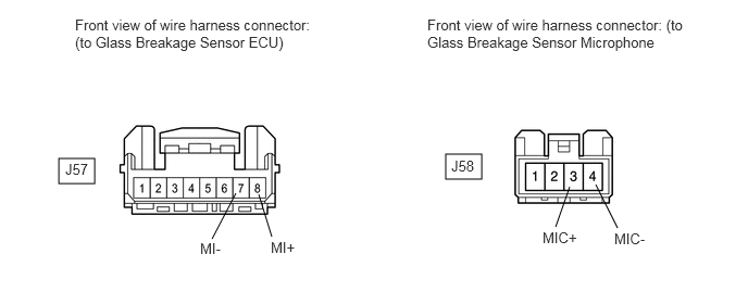
5.CHECK HARNESS AND CONNECTOR (GLASS BREAKAGE SENSOR ECU - GLASS BREAKAGE SENSOR MICROPHONE)
a.

Disconnect the J57 glass breakage sensor ECU connector.
B443064E01
4.271,1.479 4.615,1.719 0.344,0.24 0.563,1.521 0.906,1.76 0.344,0.24 2.031,2.292 2.26,1.854 false 2.604,2.271 2.479,1.865 false 5.917,2.188 5.708,1.771 false 5.323,2.177 5.458,1.792 false 0.719,0.156 3.115,0.531 2.396,0.375 10 false Front view of wire harness connector: (to Glass Breakage Sensor ECU) 4.094,0.156 6.615,0.531 2.521,0.375 10 false Front view of wire harness connector: (to Glass Breakage Sensor Microphone 1.917,2.302 2.188,2.51 0.271,0.208 10 false MI- 0.625,1.542 0.896,1.75 0.271,0.208 10 false J57 2.594,2.292 2.865,2.5 0.271,0.208 10 false MI+ 5.198,2.198 5.563,2.385 0.365,0.188 10 false MIC+ 5.885,2.208 6.25,2.396 0.365,0.188 10 false MIC- 4.323,1.51 4.594,1.719 0.271,0.208 10 false J58


b.

Disconnect the J58 glass breakage sensor microphone connector.


c.

Measure the resistance according to the value(s) in the table below.

Standard resistance:
Tester Connection Condition Specified Condition
J57-8 (MI+) - J58-3 (MIC+) Always Below 1 Ω
J57-7 (MI-) - J58-4 (MIC-)
J57-8 (MI+) or J58-3 (MIC+)- Body ground Always 10 kΩ or higher


OK

6.CHECK GLASS BREAKAGE SENSOR ECU (GLASS BREAKAGE SENSOR OUTPUT)

NG

REPAIR OR REPLACE HARNESS OR CONNECTOR

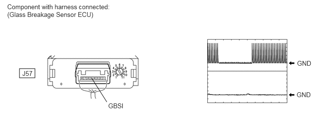
6.CHECK GLASS BREAKAGE SENSOR ECU (GLASS BREAKAGE SENSOR OUTPUT)
a.

Reconnect the J57 glass breakage sensor ECU connector.

B443065E01
0.417,1.479 0.75,1.677 0.333,0.198 2.292,2.198 1.969,1.688 false 0.156,0.063 2.667,0.448 2.51,0.385 10 false Component with harness connected: (Glass Breakage Sensor ECU) 0.479,1.5 0.76,1.677 0.281,0.177 10 false J57 2.323,2.198 2.771,2.375 0.448,0.177 10 false GBSI 6.375,1.281 6.823,1.458 0.448,0.177 10 false GND 6.365,1.958 6.813,2.135 0.448,0.177 10 false GND


b.

Reconnect the J58 glass breakage sensor microphone connector.


c.

Reconnect the J4 main body ECU connector.


d.

Turn the ignition switch ON.


e.

Using an oscilloscope, check the waveform.

Standard:
Test Connector Tool Setting Vehicle Condition Specified Condition
J57-5 (GBSI) - Body ground 1 V/DIV., 50 msec./DIV. Ignition switch ON
Tap the door glass with a hard object such as your fingernail
Pulse generation


Result
Result Proceed to
OK A
NG
(for Column Shift Type)
B
NG
(for Floor Shift Type)
C


A

REPLACE GLASS BREAKAGE SENSOR ECU

B

C