RM27M0U
_58
Vehicle Interior
_049156
ENGINE IMMOBILISER
_0234432
ENGINE IMMOBILISER SYSTEM
J
ENGINE IMMOBILISER ENGINE IMMOBILISER SYSTEM Diagnosis Circuit
DESCRIPTION
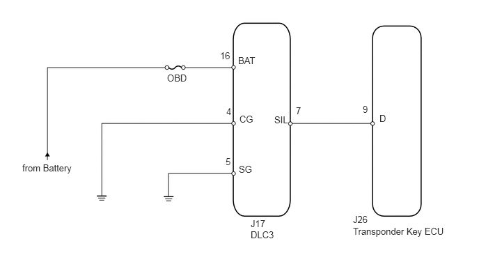
This circuit is used to read the DTCs that are output from the transponder key ECU with the Techstream.
WIRING DIAGRAM
0.333,2.427 1.292,2.885
0.958,0.458
10
false
from Battery
3.375,2.333 3.625,2.5
0.25,0.167
10
false
5
5.427,1.552 5.677,1.719
0.25,0.167
10
false
9
4.427,1.573 4.677,1.74
0.25,0.167
10
false
7
3.385,1.583 3.635,1.75
0.25,0.167
10
false
4
3.292,0.75 3.542,0.917
0.25,0.167
10
false
16
3.573,2.448 3.917,2.677
0.344,0.229
10
false
SG
3.583,1.698 3.927,1.927
0.344,0.229
10
false
CG
3.563,0.823 3.906,1.052
0.344,0.229
10
false
BAT
4.104,1.708 4.448,1.938
0.344,0.229
10
false
SIL
5.677,1.688 5.833,1.917
0.156,0.229
10
false
D
2.5,1.083 2.854,1.26
0.354,0.177
10
false
OBD
3.75,3.26 4.156,3.635
0.406,0.375
10
false
J17 DLC3
5.281,3.198 5.563,3.375
0.281,0.177
10
false
J26
5.281,3.375 6.729,3.563
1.448,0.188
10
false
Transponder Key ECU
PROCEDURE
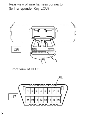
1.CHECK HARNESS AND CONNECTOR (TRANSPONDER KEY ECU - DLC3)
a.
0.469,1.844 0.844,2.104
0.375,0.26
0.344,3.74 0.719,4
0.375,0.26
1.875,2.073 2.135,2.385
false
2.167,3.531 2.323,3.156
false
0.354,0.083 2.594,0.458
2.24,0.375
10
false
Rear view of wire harness connector: (to Transponder Key ECU)
0.417,2.677 3.323,2.875
2.906,0.198
10
false
Front view of DLC3:
0.542,1.885 1,2.083
0.458,0.198
10
false
J26
0.427,3.781 0.885,3.979
0.458,0.198
10
false
J17
2.177,2.344 2.333,2.542
0.156,0.198
10
false
D
2.302,3 2.76,3.198
0.458,0.198
10
false
SIL
Disconnect the J26 ECU connector.
b.
Measure the resistance according to the value(s) in the table below.
- Standard resistance:
Tester Connection Condition Specified Condition J26-9 (D) - J17-7 (SIL) Always Below 1 Ω J26-9 (D) or J17-7 (SIL) - Body ground Always 10 kΩ or higher
OK
2.CHECK HARNESS AND CONNECTOR (DLC3 - BATTERY AND BODY GROUND)
NG
REPAIR OR REPLACE HARNESS OR CONNECTOR
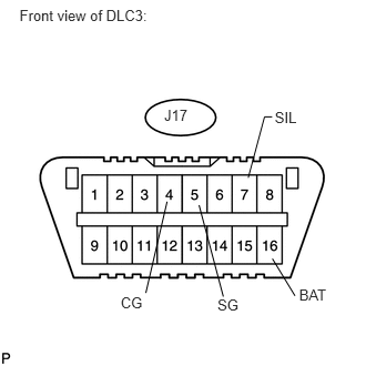
2.CHECK HARNESS AND CONNECTOR (DLC3 - BATTERY AND BODY GROUND)
a.
1.542,0.996 1.872,1.213
0.330,0.217
10
J17
1.133,2.762 1.391,2.913
0.258,0.151
10
CG
1.569,1.893 1.369,2.751
false
0.183,0.061 2.710,0.416
2.527,0.355
10
Front view of DLC3:
2.042,2.78 2.299,2.931
0.258,0.151
10
SG
1.869,1.926 2.097,2.785
false
2.809,2.687 3.217,2.839
0.408,0.151
10
BAT
2.558,2.429 2.77,2.778
false
2.58,1.02 2.855,1.247
0.275,0.227
10
SIL
2.556,1.097 2.484,1.097
2.484,1.097 2.331,1.669
false
Measure the resistance and voltage according to the value(s) in the table below.
- Standard resistance:
Tester Connection Condition Specified Condition J17-4 (CG) - Body ground Always Below 1 Ω J17-5 (SG) - Body ground
- Standard voltage:
Tester Connection Condition Specified Condition J17-16 (BAT) - Body ground Always 11 to 14 V J17-7 (SIL) - J17-5 (SG) Always Pulse generation
OK
PROCEED TO NEXT CIRCUIT INSPECTION SHOWN IN PROBLEM SYMPTOMS TABLE
NG
REPAIR OR REPLACE HARNESS OR CONNECTOR