Home › Audio / Visual / Telematics › NAVIGATION / MULTI INFO DISPLAY › NAVIGATION SYSTEM
RM27M0U _56 Audio / Visual / Telematics _049158 NAVIGATION / MULTI INFO DISPLAY _0234440 NAVIGATION SYSTEM J

NAVIGATION / MULTI INFO DISPLAY  NAVIGATION SYSTEM  Data Signal Circuit between Navigation Receiver Assembly and Extension Module  


DESCRIPTION

The stereo component tuner assembly sends the sound data signal or image data signal from a device to the navigation receiver assembly via this circuit.

WIRING DIAGRAM
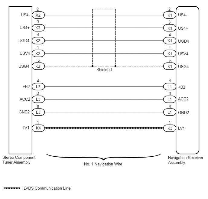
E282848E08
6.135,0.427 6.563,0.604 0.427,0.177 10 false US4- 5.771,0.438 6.198,0.615 0.427,0.177 10 false K1 5.771,0.885 6.198,1.063 0.427,0.177 10 false K1 5.771,1.323 6.198,1.5 0.427,0.177 10 false K1 5.771,1.771 6.198,1.948 0.427,0.177 10 false K1 5.771,2.198 6.198,2.375 0.427,0.177 10 false K1 5.802,0.229 5.927,0.406 0.125,0.177 10 false 2 6.135,0.885 6.563,1.063 0.427,0.177 10 false US4+ 5.802,0.677 5.927,0.854 0.125,0.177 10 false 3 6.135,1.771 6.563,1.948 0.427,0.177 10 false USV4 5.813,1.563 5.938,1.74 0.125,0.177 10 false 1 5.792,5.344 7.083,6 1.292,0.656 10 false Navigation Receiver Assembly 0.083,5.333 1.271,5.958 1.188,0.625 10 false Stereo Component Tuner Assembly 2.896,5.563 4.344,5.896 1.448,0.333 10 false No. 1 Navigation Wire 0.719,0.427 1.073,0.604 0.354,0.177 10 false US4- 0.677,0.865 1.063,1.042 0.385,0.177 10 false US4+ 0.677,1.75 1.063,1.927 0.385,0.177 10 false USV4 6.135,2.208 6.563,2.385 0.427,0.177 10 false USG4 5.833,2 5.958,2.177 0.125,0.177 10 false 5 0.635,2.198 1.063,2.375 0.427,0.177 10 false USG4 3.323,2.313 3.969,2.49 0.646,0.177 10 false Shielded 6.135,1.333 6.563,1.51 0.427,0.177 10 false UGD4 0.635,1.313 1.063,1.49 0.427,0.177 10 false UGD4 5.813,1.115 5.938,1.292 0.125,0.177 10 false 4 5.771,2.906 6.198,3.083 0.427,0.177 10 false L1 5.771,3.344 6.198,3.521 0.427,0.177 10 false L1 5.771,3.781 6.198,3.958 0.427,0.177 10 false L1 6.135,3.323 6.563,3.5 0.427,0.177 10 false ACC2 5.813,3.135 5.938,3.313 0.125,0.177 10 false 3 0.677,3.333 1.198,3.51 0.521,0.177 10 false ACC2 6.135,3.792 6.563,3.969 0.427,0.177 10 false GND2 5.813,3.583 5.938,3.76 0.125,0.177 10 false 8 0.646,3.771 1.146,3.948 0.5,0.177 10 false GND2 6.135,2.917 6.563,3.094 0.427,0.177 10 false +B2 0.781,2.896 1.208,3.073 0.427,0.177 10 false +B2 5.813,2.688 5.938,2.865 0.125,0.177 10 false 4 5.771,4.333 6.198,4.51 0.427,0.177 10 false K3 6.135,4.333 6.563,4.51 0.427,0.177 10 false LV1 0.781,4.313 1.135,4.49 0.354,0.177 10 false LV1 5.813,4.125 5.938,4.302 0.125,0.177 10 false 1 1.229,0.438 1.656,0.615 0.427,0.177 10 false K2 1.219,0.875 1.646,1.052 0.427,0.177 10 false K2 1.219,1.313 1.646,1.49 0.427,0.177 10 false K2 1.219,1.76 1.646,1.938 0.427,0.177 10 false K2 1.219,2.198 1.646,2.375 0.427,0.177 10 false K2 1.26,0.229 1.385,0.406 0.125,0.177 10 false 2 1.271,0.667 1.396,0.844 0.125,0.177 10 false 3 1.271,1.552 1.396,1.729 0.125,0.177 10 false 1 1.292,1.99 1.417,2.167 0.125,0.177 10 false 5 1.271,1.104 1.396,1.281 0.125,0.177 10 false 4 1.24,2.906 1.667,3.083 0.427,0.177 10 false L3 1.24,3.333 1.667,3.51 0.427,0.177 10 false L3 1.24,3.781 1.667,3.958 0.427,0.177 10 false L3 1.271,3.125 1.396,3.302 0.125,0.177 10 false 3 1.271,3.583 1.396,3.76 0.125,0.177 10 false 8 1.271,2.698 1.396,2.875 0.125,0.177 10 false 4 1.24,4.323 1.667,4.5 0.427,0.177 10 false K4 1.271,4.125 1.396,4.302 0.125,0.177 10 false 1 0.74,6.396 2.635,6.698 1.896,0.302 10 false : LVDS Communication Line

CAUTION / NOTICE / HINT

NOTICE:

After replacing the stereo component tuner assembly of vehicles subscribed to pay-type satellite radio broadcasts, XM radio ID registration is necessary.


PROCEDURE

1.CHECK HARNESS AND CONNECTOR (NAVIGATION RECEIVER ASSEMBLY - STEREO COMPONENT TUNER ASSEMBLY)
a.

Disconnect the K1 and L1 navigation receiver assembly connectors.


b.

Disconnect the K2 and L3 stereo component tuner assembly connector.


c.

Measure the resistance according to the value(s) in the table below.

Standard Resistance:
Tester Connection Condition Specified Condition
K1-1 (USV4) - K2-1 (USV4) Always Below 1 Ω
K1-2 (US4-) - K2-2 (US4-) Always Below 1 Ω
K1-3 (US4+) - K2-3 (US4+) Always Below 1 Ω
K1-4 (UGD4) - K2-4 (UGD4) Always Below 1 Ω
K1-5 (USG4) - K2-5 (USG4) Always Below 1 Ω
L1-4 (+B2) - L3-4 (+B2) Always Below 1 Ω
L1-3 (ACC2) - L3-3 (ACC2) Always Below 1 Ω
L1-8 (GND2) - L3-8 (GND2) Always Below 1 Ω
K1-1 (USV4) - Body ground Always 10 kΩ or higher
K1-2 (US4-) - Body ground Always 10 kΩ or higher
K1-3 (US4+) - Body ground Always 10 kΩ or higher
K1-4 (UGD4) - Body ground Always 10 kΩ or higher
K1-5 (USG4) - Body ground Always 10 kΩ or higher
L1-4 (+B2) - Body ground Always 10 kΩ or higher
L1-3 (ACC2) - Body ground Always 10 kΩ or higher
L1-8 (GND2) - Body ground Always 10 kΩ or higher


OK

2.CHECK NO. 1 NAVIGATION WIRE

NG

REPAIR OR REPLACE HARNESS OR CONNECTOR

2.CHECK NO. 1 NAVIGATION WIRE
a.

b.

Check that the malfunction disappears.

OK:

Malfunction disappears.


OK

END (NO. 1 NAVIGATION WIRE IS DEFECTIVE)

NG

PROCEED TO NEXT SUSPECTED AREA SHOWN IN PROBLEM SYMPTOMS TABLE