RM27M0U
_56
Audio / Visual / Telematics
_049159
PARK ASSIST / MONITORING
_0234441
INTUITIVE PARKING ASSIST SYSTEM
J
PARK ASSIST / MONITORING INTUITIVE PARKING ASSIST SYSTEM Vehicle Speed Signal Circuit
WIRING DIAGRAM
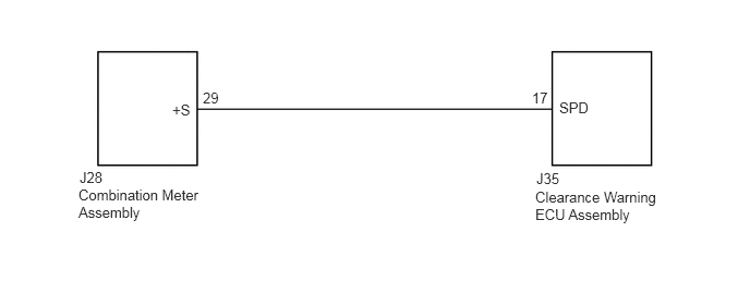
5.125,1.625 5.698,1.802
0.573,0.177
10
false
J35
5.344,0.948 5.917,1.125
0.573,0.177
10
false
SPD
5.083,0.854 5.26,1.031
0.177,0.177
10
false
17
1.646,0.969 1.917,1.146
0.271,0.177
10
false
+S
1.938,0.854 2.156,1.031
0.219,0.177
10
false
29
5.115,1.802 6.469,2.188
1.354,0.385
10
false
Clearance Warning ECU Assembly
0.76,1.615 1.333,1.792
0.573,0.177
10
false
J28
0.75,1.781 2.094,2.125
1.344,0.344
10
false
Combination Meter Assembly
PROCEDURE
1.CHECK COMBINATION METER ASSEMBLY (SPEED SIGNAL)
a.
1.677,1.406 2.74,1.896
2.74,1.896 2.844,1.896
true
2.854,3.396 3.219,3.552
0.365,0.156
10
false
GND
1.615,0.521 1.896,0.677
0.281,0.156
10
false
J35
2.927,1.813 3.24,1.969
0.313,0.156
10
false
SPD
0.104,2.125 1.115,2.313
1.01,0.188
10
false
*b
0.104,0.073 0.354,0.344
0.25,0.271
10
false
*a
Disconnect the clearance warning ECU assembly connector.
b.
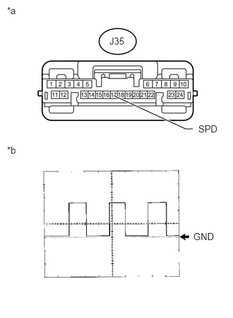
Using an oscilloscope, check the signal waveform of the combination meter assembly.
| Item | Content |
|---|---|
| Terminal No. (Symbol) | J35-17 (SPD) - Body ground |
| Tool Setting | 5 V/DIV., 20 msec./DIV. |
| Condition | Drive vehicle at 20 km/h (12 mph) |
- OK:
Refer to the illustration.
- HINT:
-
As the vehicle speed increases, the wave length shortens.
| *a | Front view of wire harness connector
(to Clearance Warning ECU Assembly) |
| *b | Waveform |
OK
PROCEED TO NEXT SUSPECTED AREA SHOWN IN PROBLEM SYMPTOMS TABLE
NG
2.CHECK HARNESS AND CONNECTOR (CLEARANCE WARNING ECU ASSEMBLY - COMBINATION METER ASSEMBLY)
2.CHECK HARNESS AND CONNECTOR (CLEARANCE WARNING ECU ASSEMBLY - COMBINATION METER ASSEMBLY)
a.
Disconnect the J35 clearance warning ECU assembly connector.
b.
Disconnect the J28 combination meter assembly connector.
c.
Measure the resistance according to the value(s) in the table below.
- Standard Resistance:
Tester Connection Condition Specified Condition J35-17 (SPD) - J28-29 (+S) Always Below 1 Ω J35-17 (SPD) - Body ground Always 10 kΩ or higher
OK
GO TO METER / GAUGE SYSTEM
(See pageVehicle Interior>METER / GAUGE / DISPLAY>METER / GAUGE SYSTEM>HOW TO PROCEED WITH TROUBLESHOOTING)
NG
REPAIR OR REPLACE HARNESS OR CONNECTOR