RM27M0U
_56
Audio / Visual / Telematics
_049159
PARK ASSIST / MONITORING
_0234446
CLEARANCE SONAR MAIN SWITCH
G
PARK ASSIST / MONITORING CLEARANCE SONAR MAIN SWITCH INSPECTION
PROCEDURE

 84490A
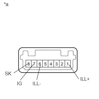
1.INSPECT BACK SONAR OR CLEARANCE SONAR SWITCH ASSEMBLY
a.
0.133,0.048 0.668,0.389
0.536,0.341
12
*a
2.785,2.643 3.191,2.859
0.406,0.216
12
ILL+
2.396,2.243 2.734,2.741
false
1.405,2.248 1.274,2.769
false
1.154,2.237 0.707,2.779
false
0.946,2.225 0.477,2.534
false
1.13,2.792 1.536,3.008
0.406,0.216
12
ILL-
0.585,2.798 0.991,3.014
0.406,0.216
12
IG
0.169,2.454 0.574,2.670
0.406,0.216
12
SK
Measure the resistance according to the value(s) in the table below.
- Standard Resistance:
Tester Connection Switch Condition Specified Condition 7 (IG) - 8 (SK) Sonar switch off 10 kΩ or higher Sonar switch on Below 1 Ω
If the result is not as specified, replace the back sonar or clearance sonar switch assembly.
b.
Check that the switch illuminates.
- OK:
Tester Connection Specified Condition Battery positive (+) → Terminal 1 (ILL+)
Battery negative (-) → Terminal 6 (ILL-)Illuminates
If the result is not as specified, replace the back sonar or clearance sonar switch assembly.
| *a | Component without harness connected
(Back Sonar or Clearance Sonar Switch Assembly) |