Home › Vehicle Interior › MIRROR › POWER MIRROR CONTROL SYSTEM(w/ Memory)
RM27M0U _58 Vehicle Interior _049162 MIRROR _0234477 POWER MIRROR CONTROL SYSTEM(w/ Memory) J

MIRROR  POWER MIRROR CONTROL SYSTEM(w/ Memory)  Driver Side Power Mirror cannot be Adjusted with Power Mirror Switch  


SYSTEM DESCRIPTION

This circuit detects the conditions of the outer mirror switch.

The outer mirror switch sends information about the operating condition of the mirror switch (switch input signals) through the CAN communication line. Then the switch input signals are sent to the outer mirror control ECU. Mirror adjustment is controlled by the outer mirror control ECU.

WIRING DIAGRAM
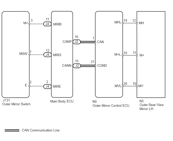
B166096E05
0.115,4.063 0.448,4.24 0.333,0.177 10 false J131 2.594,1.635 3,1.813 0.406,0.177 10 false CANP 2.573,2.625 2.979,2.802 0.406,0.177 10 false CANN 1.229,3.313 1.385,3.49 0.156,0.177 10 false 2 1.271,0.76 1.427,0.938 0.156,0.177 10 false 3 4.021,1.646 4.427,1.823 0.406,0.177 10 false CAN 4.031,2.625 4.49,2.802 0.458,0.177 10 false CGND 4.74,0.833 5.177,1.01 0.438,0.177 10 false MHL 4.74,2.167 5.156,2.344 0.417,0.177 10 false M+L 4.75,3.469 5.177,3.646 0.427,0.177 10 false MVL 5.781,4.094 6.896,4.74 1.115,0.646 10 false N5 0.833,5.302 2.563,5.479 1.729,0.177 10 false : CAN Communication Line 3.094,1.438 3.302,1.615 0.208,0.177 10 false 16 3.104,2.438 3.271,2.615 0.167,0.177 10 false 15 3.094,1.635 3.271,1.802 0.177,0.167 10 false J2 3.125,2.635 3.292,2.813 0.167,0.177 10 false J2 5.115,0.76 5.333,0.938 0.219,0.177 10 false 19 5.115,2.104 5.281,2.281 0.167,0.177 10 false 18 5.115,3.375 5.333,3.552 0.219,0.177 10 false 20 0.969,0.865 1.219,1.083 0.25,0.219 10 false M+ 1.031,3.438 1.188,3.615 0.156,0.177 10 false E 1.885,0.906 2.052,1.083 0.167,0.177 10 false J4 1.896,3.49 2.063,3.667 0.167,0.177 10 false J4 1.896,0.708 2.063,0.885 0.167,0.177 10 false 11 1.917,3.302 2.042,3.469 0.125,0.167 10 false 2 2.208,0.917 2.573,1.094 0.365,0.177 10 false MIRB 2.188,3.49 2.552,3.667 0.365,0.177 10 false MIRE 3.833,1.49 3.99,1.667 0.156,0.177 10 false 1 3.76,2.469 3.927,2.646 0.167,0.177 10 false 21 2.083,4.104 3.083,4.281 1,0.177 10 false Main Body ECU 3.833,4.115 4.031,4.302 0.198,0.188 10 false N8 5.781,2.198 6.021,2.385 0.24,0.188 10 false M+ 5.5,2.094 5.667,2.271 0.167,0.177 10 false 11 5.75,0.865 5.979,1.042 0.229,0.177 10 false MH 5.479,0.76 5.646,0.938 0.167,0.177 10 false 12 5.729,3.469 5.958,3.646 0.229,0.177 10 false MV 5.49,3.375 5.656,3.552 0.167,0.177 10 false 10 1.229,2.052 1.385,2.229 0.156,0.177 10 false 1 1.896,2.177 2.063,2.354 0.167,0.177 10 false J4 1.896,2 2.063,2.177 0.167,0.177 10 false 12 2.198,2.188 2.563,2.365 0.365,0.177 10 false MIRS 0.802,2.135 1.156,2.313 0.354,0.177 10 false MSW 5.781,4.25 6.865,4.583 1.083,0.333 10 false Outer Rear View Mirror LH 0.094,4.219 1.302,4.396 1.208,0.177 10 false Outer Mirror Switch 3.833,4.281 5.406,4.458 1.573,0.177 10 false Outer Mirror Control ECU

PROCEDURE

1.CHECK DTC
a.

Use the Techstream to check if the CAN communication system is functioning normally (see page Power Source / Network>CAN COMMUNICATION>CAN COMMUNICATION SYSTEM>DIAGNOSIS SYSTEM).

Result
Result Proceed to
CAN DTC is not output A
CAN DTC is output B


A

2.READ VALUE USING TECHSTREAM (OUTER MIRROR SWITCH)

B

2.READ VALUE USING TECHSTREAM (OUTER MIRROR SWITCH)
a.

Check the DATA LIST for proper functioning of the outer mirror switch.


Main body
Tester Display Measurement Item/Range Normal Condition Diagnostic Note
Mirror Selection SW (Left) Mirror master switch signal for LH mirror / ON or OFF ON: Switch is in L position
OFF: Switch is OFF or in R position
-
Mirror Position SW (Right) Mirror control switch signal (RIGHT) / ON or OFF ON: RIGHT switch is ON
OFF: Any switch except RIGHT is ON or all switches are OFF
-
Mirror Position SW (Left) Mirror control switch signal (LEFT) / ON or OFF ON: LEFT switch is ON
OFF: Any switch except LEFT is ON or all switches are OFF
-
Mirror Position SW (UP) Mirror control switch signal (UP) / ON or OFF ON: UP switch is ON
OFF: Any switch except UP is ON or all switches are OFF
-
Mirror Position SW (Down) Mirror control switch signal (DOWN) / ON or OFF ON: DOWN switch is ON
OFF: Any switch except DOWN is ON or all switches are OFF
-

OK:

On screen, each item changes between ON and OFF according to above chart.


OK

3.INSPECT OUTER REAR VIEW MIRROR LH

NG

5.INSPECT OUTER MIRROR SWITCH ASSEMBLY
3.INSPECT OUTER REAR VIEW MIRROR LH
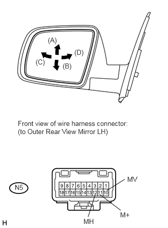
a.
U151930E02
2.188,3.906 2.552,3.677 false 2.042,3.99 2.469,4.313 false 1.948,3.99 1.802,4.448 false 0.979,0.74 1.177,0.917 0.198,0.177 10 false (A) 1.281,1.271 1.479,1.448 0.198,0.177 10 false (B) 0.729,1.188 0.938,1.365 0.208,0.177 10 false (C) 1.521,0.99 1.729,1.167 0.208,0.177 10 false (D) 0.365,2.448 2.688,2.792 2.323,0.344 10 false Front view of wire harness connector: (to Outer Rear View Mirror LH) 0.302,3.76 0.5,3.938 0.198,0.177 10 false N5 2.604,3.594 2.833,3.771 0.229,0.177 10 false MV 2.458,4.323 2.677,4.5 0.219,0.177 10 false M+ 1.708,4.458 1.938,4.635 0.229,0.177 10 false MH

Remove the mirror LH (see page Vehicle Interior>MIRROR>OUTER REAR VIEW MIRROR>REMOVAL).


b.

Apply battery voltage and check the operation of the power mirror.

OK:
Measurement Condition Specified Condition
Battery positive (+) → Terminal 10 (MV)
Battery negative (-) → Terminal 11 (M+)
Turns upward (A)
Battery negative (-) → Terminal 10 (MV)
Battery positive (+) → Terminal 11 (M+)
Turns downward (B)
Battery positive (+) → Terminal 12 (MH)
Battery negative (-) → Terminal 11 (M+)
Turns left (C)
Battery negative (-) → Terminal 12 (MH)
Battery positive (+) → Terminal 11 (M+)
Turns right (D)


OK

4.CHECK HARNESS AND CONNECTOR (OUTER MIRROR CONTROL ECU - OUTER REAR VIEW MIRROR LH)

NG

REPLACE OUTER REAR VIEW MIRROR LH

4.CHECK HARNESS AND CONNECTOR (OUTER MIRROR CONTROL ECU - OUTER REAR VIEW MIRROR LH)
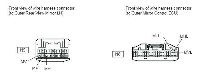
a.

Disconnect the N8 ECU connector.

B443020E01
0.583,1.594 0.958,1.792 0.375,0.198 3.781,1.729 4.156,1.927 0.375,0.198 0.958,2.042 1.292,1.885 false 1.25,2.188 1.448,1.906 false 1.563,2.198 1.563,1.906 false 5.854,1.729 6.115,1.323 false 5.792,1.74 5.5,1.25 false 5.948,1.76 6.146,1.76 false 0.292,0.188 2.552,0.521 2.26,0.333 10 false Front view of wire harness connector: (to Outer Rear View Mirror LH) 4.229,0.188 6.49,0.521 2.26,0.333 10 false Front view of wire harness connector: (to Outer Mirror Control ECU) 0.677,1.604 0.906,1.792 0.229,0.188 10 false N5 3.875,1.74 4.104,1.927 0.229,0.188 10 false N8 0.698,2 0.927,2.188 0.229,0.188 10 false MV 1.49,2.24 1.719,2.427 0.229,0.188 10 false MH 1.083,2.219 1.313,2.406 0.229,0.188 10 false M+ 5.125,1.125 5.438,1.313 0.313,0.188 10 false M+L 6.052,1.135 6.365,1.302 0.313,0.167 10 false MHL 6.188,1.677 6.5,1.844 0.313,0.167 10 false MVL


b.

Disconnect the N5 mirror connector.


c.

Measure the resistance according to the value(s) in the table below.

Standard resistance:
Tester Connection Condition Specified Condition
N8-18 (M+L) - N5-11 (M+) Always Below 1 Ω
N8-19 (MHL) - N5-12 (MH)
N8-20 (MVL) - N5-10 (MV)
N5-11 (M+) - Body ground Always 10 kΩ or higher
N5-12 (MH) - Body ground
N5-10 (MV) - Body ground


OK

NG
REPAIR OR REPLACE HARNESS OR CONNECTOR

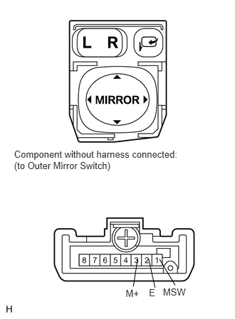
5.INSPECT OUTER MIRROR SWITCH ASSEMBLY
a.
B167772E01
0.206,2.18 2.670,2.528 2.465,0.348 10 Component without harness connected: (to Outer Mirror Switch) 2.179,4.204 2.335,4.385 0.156,0.181 10 E 2.173,3.797 2.268,4.218 false 1.838,4.217 2.156,4.398 0.318,0.181 10 M+ 2.013,3.792 1.95,4.201 false 2.332,3.799 2.562,4.182 false 2.384,4.201 2.764,4.382 0.380,0.181 10 MSW

Remove the switch (see page Vehicle Interior>MIRROR>OUTER MIRROR SWITCH>REMOVAL).


b.

Measure the resistance according to the value(s) in the table below.

Standard resistance:
Tester Connection Switch Condition Specified Condition
3 (M+) - 2 (E) UP switch pushed 100 Ω
DOWN switch pushed 470 Ω
LEFT switch pushed 800 Ω
RIGHT switch pushed 250 Ω
1 (MSW) - 2 (E) No switches pushed 10 kΩ or higher
L switch pushed 100 Ω


OK

6.CHECK HARNESS AND CONNECTOR (OUTER MIRROR SWITCH - MAIN BODY ECU)

NG

REPLACE OUTER MIRROR SWITCH ASSEMBLY

6.CHECK HARNESS AND CONNECTOR (OUTER MIRROR SWITCH - MAIN BODY ECU)
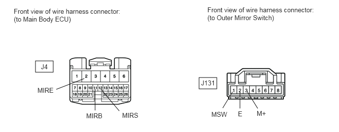
a.

Disconnect the J4 ECU connector.

B443022E01
0.75,1.292 1.125,1.531 0.375,0.24 4.208,1.646 4.583,1.885 0.375,0.24 1.188,1.896 1.781,1.667 false 2.01,2.344 2.01,1.885 false 2.521,2.354 2.135,1.896 false 4.708,2.292 4.917,1.948 false 5.073,2.302 5.073,1.948 false 5.448,2.302 5.229,1.948 false 0.292,0.156 2.573,0.51 2.281,0.354 10 false Front view of wire harness connector: (to Main Body ECU) 0.865,1.333 1.042,1.521 0.177,0.188 10 false J4 0.792,1.833 1.146,2.021 0.354,0.188 10 false MIRE 1.823,2.375 2.177,2.563 0.354,0.188 10 false MIRB 2.583,2.365 2.938,2.552 0.354,0.188 10 false MIRS 4.385,0.125 6.667,0.479 2.281,0.354 10 false Front view of wire harness connector: (to Outer Mirror Switch) 4.25,1.677 4.542,1.854 0.292,0.177 10 false J131 4.469,2.344 4.823,2.531 0.354,0.188 10 false MSW 5.031,2.333 5.167,2.521 0.135,0.188 10 false E 5.427,2.323 5.667,2.51 0.24,0.188 10 false M+


b.

Disconnect the J131 switch connector.


c.

Measure the resistance according to the value(s) in the table below.

Standard resistance:
Tester Connection Condition Specified Condition
J4-2 (MIRE) - J131-2 (E) Always Below 1 Ω
J4-11 (MIRB) - J131-3 (M+) Always Below 1 Ω
J4-12 (MIRS) - J131-1 (MSW) Always Below 1 Ω
J131-3 (M+) - Body ground Always 10 kΩ or higher
J131-2 (E) - Body ground Always 10 kΩ or higher
J131-1 (MSW) - Body ground Always 10 kΩ or higher


OK

REPLACE MAIN BODY ECU

NG

REPAIR OR REPLACE HARNESS OR CONNECTOR