MIRROR POWER MIRROR CONTROL SYSTEM(w/ Memory) Power Retractable Mirrors do not Operate with Power Retract Mirror Switch
SYSTEM DESCRIPTION
This circuit detects the conditions of the mirror retract switch.
The outer mirror switch sends information about the operating condition of the mirror retract switch (switch input signals) through the CAN communication line. Then the switch input signals are sent to the outer mirror control ECU.
WIRING DIAGRAM
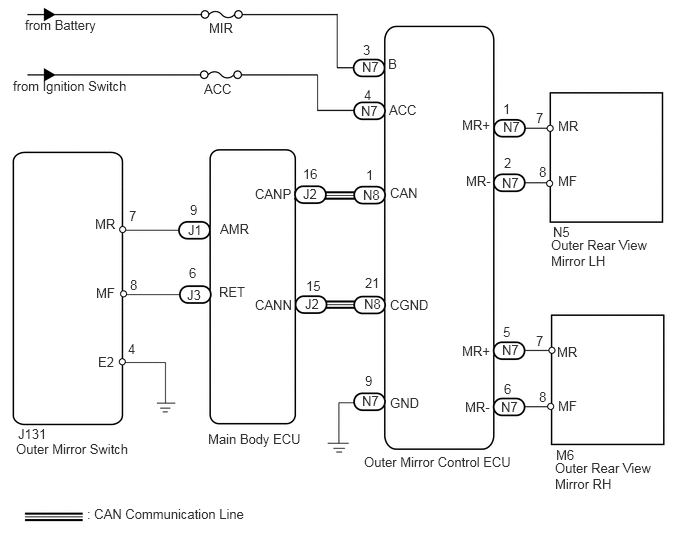
PROCEDURE
Use the Techstream to check if the CAN communication system is functioning normally (see page Power Source / Network>CAN COMMUNICATION>CAN COMMUNICATION SYSTEM>DIAGNOSIS SYSTEM).
| Result | Proceed to |
|---|---|
| CAN DTC is not output | A |
| CAN DTC is output | B |
A
B
Operate the retract switch, and check that the outer rear view mirror operates.
| Result | Proceed to |
|---|---|
| Neither side operates | A |
| LH side does not operate | B |
| RH side does not operate | C |
A
B
C
Check the DATA LIST for proper functioning of the mirror retract switch.
| Tester Display | Measurement Item/Range | Normal Condition | Diagnostic Note |
|---|---|---|---|
| Outer Mirror Fold SW | Mirror retract switch signal / ON or OFF | ON: Switch is ON (retracting)
OFF: Switch is OFF |
- |
OK
NG
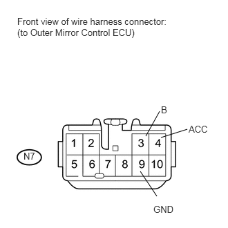
Disconnect the N7 ECU connector.
Measure the resistance according to the value(s) in the table below.
- Standard resistance:
Tester Connection Condition Specified Condition N7-9 (GND) - Body ground Always Below 1 Ω
Measure the voltage according to the value(s) in the table below.
- Standard voltage:
Tester Connection Switch Condition Specified Condition N7-3 (B) - Body ground Always 11 to 14 V N7-4 (ACC) - Body ground Ignition switch LOCK Below 1 V Ignition switch ACC 11 to 14 V
OK
NG
Temporarily replace the outer mirror control ECU with a normal one. (see page Vehicle Interior>ENGINE HOOD / DOOR>FRONT DOOR(for Regular Cab)>DISASSEMBLY)
Check that the outer rear view mirror operates normally.
- OK:
Outer rear view mirror operates normally.
OK
NG
Remove the mirror LH (see page Vehicle Interior>MIRROR>OUTER REAR VIEW MIRROR>REMOVAL).
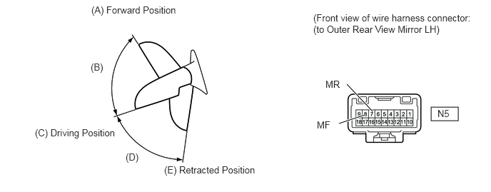
For each mirror position: Disconnect the battery, set the mirror position by hand, connect the battery, and check the retractable mirror's movement.
- NOTICE:
- ·
Disconnect and reconnect the battery once between each mirror position check.
·The mirror position cannot be changed manually when the battery is connected. To change the mirror position manually, the battery must be disconnected first.
- OK:
Measurement Condition Mirror Position Specified Condition Battery positive (+) → Terminal 7 (MR)
Battery negative (-) → Terminal 8 (MF)Forward position (A) Moves from (A) to retracted position (E) Battery negative (-) → Terminal 7 (MR)
Battery positive (+) → Terminal 8 (MF)Forward position (A) Does not move Battery positive (+) → Terminal 7 (MR)
Battery negative (-) → Terminal 8 (MF)Position between forward position (A) and driving position (C) Moves from (B) to retracted position (E) Battery negative (-) → Terminal 7 (MR)
Battery positive (+) → Terminal 8 (MF)Position between forward position (A) and driving position (C) Moves from (B) to forward position (A) Battery positive (+) → Terminal 7 (MR)
Battery negative (-) → Terminal 8 (MF)Driving position (C) Moves from (C) to retracted position (E) Battery negative (-) → Terminal 7 (MR)
Battery positive (+) → Terminal 8 (MF)Driving position (C) Does not move Battery positive (+) → Terminal 7 (MR)
Battery negative (-) → Terminal 8 (MF)Position between driving position (C) and retracted position (E) Moves from (D) to retracted position (E) Battery negative (-) → Terminal 7 (MR)
Battery positive (+) → Terminal 8 (MF)Position between driving position (C) and retracted position (E) Moves from (D) to driving position (C) Battery positive (+) → Terminal 7 (MR)
Battery negative (-) → Terminal 8 (MF)Retracted position (E) Does not move Battery negative (-) → Terminal 7 (MR)
Battery positive (+) → Terminal 8 (MF)Retracted position (E) Moves from (E) to driving position (C)
OK
NG
Disconnect the N7 ECU connector.
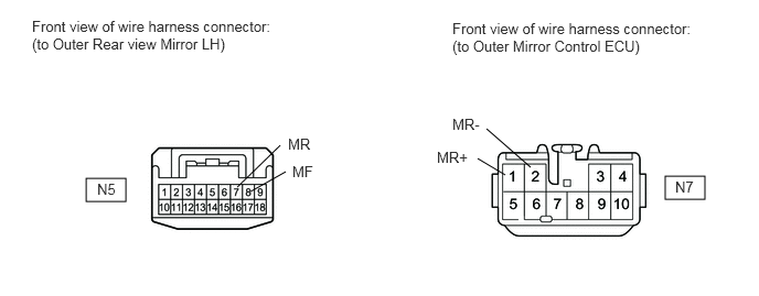
Disconnect the N5 mirror connector.
Measure the resistance according to the value(s) in the table below.
- Standard resistance:
Tester Connection Condition Specified Condition N7-1 (MR+) - N5-7 (MR) Always Below 1 Ω N7-2 (MR-) - N5-8 (MF) N5-7 (MR) - Body ground Always 10 kΩ or higher N5-8 (MF) - Body ground
OK
NG
Remove the mirror RH (see page Vehicle Interior>MIRROR>OUTER REAR VIEW MIRROR>REMOVAL).
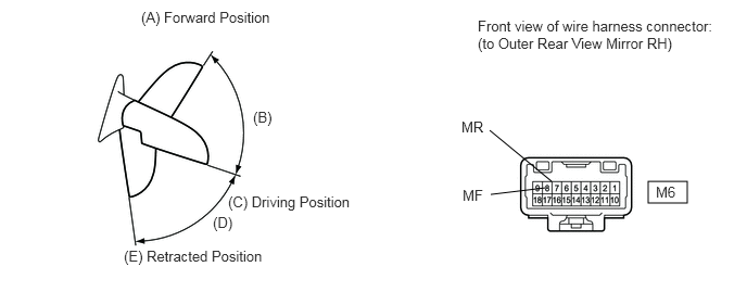
For each mirror position: Disconnect the battery, set the mirror position by hand, connect the battery, and check the retractable mirror's movement.
- NOTICE:
- ·
Disconnect and reconnect the battery once between each mirror position check.
·The mirror position cannot be changed manually when the battery is connected. To change the mirror position manually, the battery must be disconnected first.
- OK:
Measurement Condition Mirror Position Specified Condition Battery positive (+) → Terminal 7 (MR)
Battery negative (-) → Terminal 8 (MF)Forward position (A) Moves from (A) to retracted position (E) Battery negative (-) → Terminal 7 (MR)
Battery positive (+) → Terminal 8 (MF)Forward position (A) Does not move Battery positive (+) → Terminal 7 (MR)
Battery negative (-) → Terminal 8 (MF)Position between forward position (A) and driving position (C) Moves from (B) to retracted position (E) Battery negative (-) → Terminal 7 (MR)
Battery positive (+) → Terminal 8 (MF)Position between forward position (A) and driving position (C) Moves from (B) to forward position (A) Battery positive (+) → Terminal 7 (MR)
Battery negative (-) → Terminal 8 (MF)Driving position (C) Moves from (C) to retracted position (E) Battery negative (-) → Terminal 7 (MR)
Battery positive (+) → Terminal 8 (MF)Driving position (C) Does not move Battery positive (+) → Terminal 7 (MR)
Battery negative (-) → Terminal 8 (MF)Position between driving position (C) and retracted position (E) Moves from (D) to retracted position (E) Battery negative (-) → Terminal 7 (MR)
Battery positive (+) → Terminal 8 (MF)Position between driving position (C) and retracted position (E) Moves from (D) to driving position (C) Battery positive (+) → Terminal 7 (MR)
Battery negative (-) → Terminal 8 (MF)Retracted position (E) Does not move Battery negative (-) → Terminal 7 (MR)
Battery positive (+) → Terminal 8 (MF)Retracted position (E) Moves from (E) to driving position (C)
OK
NG
Disconnect the N7 ECU connector.
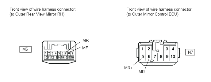
Disconnect the M6 mirror connector.
Measure the resistance according to the value(s) in the table below.
- Standard resistance:
Tester Connection Condition Specified Condition N7-5 (MR+) - M6-7 (MR) Always Below 1 Ω N7-6 (MR-) - M6-8 (MF) M6-7 (MR) - Body ground Always 10 kΩ or higher M6-8 (MF) - Body ground
OK
NG
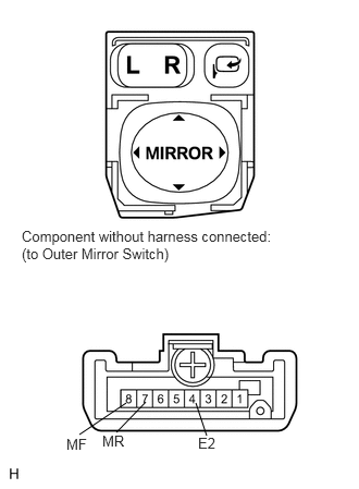
Remove the switch (see page Vehicle Interior>MIRROR>OUTER MIRROR SWITCH>REMOVAL).
Measure the resistance according to the value(s) in the table below.
- Standard resistance:
Tester Connection Switch Condition Specified Condition 4 (E2) - 7 (MR) Pressed (Retracts) 10 kΩ or higher Not pressed Below 1 Ω 4 (E2) - 8 (MF) Pressed (Returns) Below 1 Ω Not pressed 10 kΩ or higher
OK
NG
Disconnect the J1 and J3 ECU connectors.
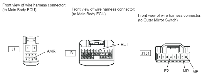
Disconnect the J131 switch connector.
Measure the resistance according to the value(s) in the table below.
- Standard resistance:
Tester Connection Condition Specified Condition J1-9 (AMR) - J131-7 (MR) Always Below 1 Ω J3-6 (RET) - J131-8 (MF) J131-4 (E2) - Body ground J131-7 (MR) - Body ground Always 10 kΩ or higher J131-8 (MF) - Body ground
OK
NG