Home › Vehicle Interior › SLIDING ROOF › SLIDING ROOF SYSTEM
RM27M0U _58 Vehicle Interior _049166 SLIDING ROOF _0234506 SLIDING ROOF SYSTEM C

SLIDING ROOF  SLIDING ROOF SYSTEM  B2343  Position Initialization Incomplete  


DESCRIPTION

This DTC is output when the sliding roof drive gear (sliding roof ECU) has not been initialized.

DTC Code DTC Detection Condition Trouble Area
B2343 Sliding roof drive gear (sliding roof ECU) has not been initialized
·

Sliding roof switch

·

Roof console box

·

Harness and connector

·

Sliding roof drive gear (sliding roof ECU)


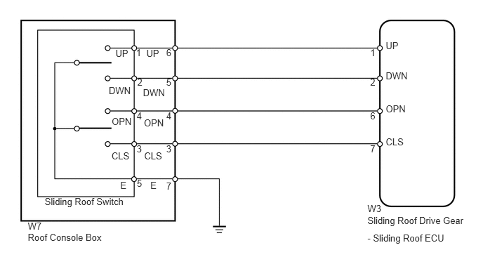
WIRING DIAGRAM

B167040E02
5.452,3.006 5.765,3.185 0.313,0.179 10 W3 2.231,2.663 2.401,2.819 0.170,0.156 10 E 1.785,2.663 1.955,2.819 0.170,0.156 10 E 2.466,2.121 2.673,2.309 0.207,0.188 10 3 2.027,2.121 2.234,2.309 0.207,0.188 10 3 2.031,2.635 2.238,2.823 0.207,0.188 10 5 2.139,2.232 2.471,2.388 0.332,0.156 10 CLS 1.654,2.232 1.985,2.388 0.332,0.156 10 CLS 2.135,1.741 2.460,1.897 0.325,0.156 10 OPN 1.657,1.718 1.981,1.874 0.325,0.156 10 OPN 2.121,1.291 2.480,1.447 0.360,0.156 10 DWN 1.614,1.263 1.987,1.419 0.373,0.156 10 DWN 5.723,0.592 6.351,0.748 0.628,0.156 10 UP 5.723,2.026 6.351,2.182 0.628,0.156 10 CLS 5.723,1.536 6.351,1.692 0.628,0.156 10 OPN 5.723,1.039 6.351,1.195 0.628,0.156 10 DWN 2.172,0.704 2.420,0.860 0.248,0.156 10 UP 1.714,0.704 1.963,0.860 0.248,0.156 10 UP 5.452,3.192 6.953,3.361 1.501,0.169 10 Sliding Roof Drive Gear 5.452,3.447 6.685,3.621 1.233,0.174 10 - Sliding Roof ECU 5.493,1.635 5.646,1.824 0.153,0.188 10 6 5.493,1.138 5.646,1.326 0.153,0.188 10 2 2.037,1.138 2.190,1.326 0.153,0.188 10 2 5.493,0.696 5.646,0.884 0.153,0.188 10 1 2.018,0.696 2.171,0.884 0.153,0.188 10 1 5.493,2.121 5.646,2.309 0.153,0.188 10 7 2.466,1.635 2.673,1.824 0.207,0.188 10 4 2.027,1.635 2.234,1.824 0.207,0.188 10 4 2.466,1.138 2.673,1.326 0.207,0.188 10 5 2.466,0.696 2.673,0.884 0.207,0.188 10 6 2.466,2.679 2.673,2.867 0.207,0.188 10 7 0.412,3.273 0.706,3.429 0.295,0.156 10 W7 0.412,3.435 2.114,3.591 1.702,0.156 10 Roof Console Box 0.663,2.908 1.921,3.092 1.258,0.184 10 Sliding Roof Switch

PROCEDURE

1.INITIALIZE SLIDING ROOF DRIVE GEAR SUB-ASSEMBLY (SLIDING ROOF ECU)
a.

Check that the sliding roof drive gear can be initialized (see page Vehicle Interior>SLIDING ROOF>SLIDING ROOF SYSTEM>INITIALIZATION).

OK:

Sliding roof drive gear can be initialized.


OK

2.CHECK FOR DTC

NG

3.CHECK HARNESS AND CONNECTOR (SLIDING ROOF ECU - ROOF CONSOLE BOX)
2.CHECK FOR DTC

b.

Check for DTCs (see page Vehicle Interior>SLIDING ROOF>SLIDING ROOF SYSTEM>DTC CHECK / CLEAR).

Result
Result Proceed to
No DTC is output A
DTC B2343 is output B


A

END

B

REPLACE SLIDING ROOF DRIVE GEAR SUB-ASSEMBLY (SLIDING ROOF ECU)

3.CHECK HARNESS AND CONNECTOR (SLIDING ROOF ECU - ROOF CONSOLE BOX)
a.
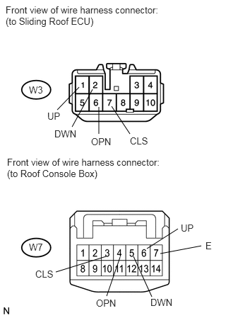
U151979E02
0.844,1.615 1.167,1.281 false 2.167,3.656 2.625,3.365 false 1.063,1.865 1.365,1.313 false 2.24,4.365 1.969,3.771 false 0.823,4 1.563,3.771 false 1.573,4.354 1.771,3.781 false 2.969,3.615 2.365,3.729 false 1.917,1.969 1.646,1.563 false 1.458,1.573 1.458,1.969 false 0.083,0.063 2.375,0.427 2.292,0.365 10 false Front view of wire harness connector: (to Sliding Roof ECU) 0.104,2.302 2.354,2.656 2.25,0.354 10 false Front view of wire harness connector: (to Roof Console Box) 0.427,1.24 0.729,1.406 0.302,0.167 10 false W3 1.344,2 1.792,2.167 0.448,0.167 10 false OPN 1.417,4.375 1.854,4.542 0.438,0.167 10 false OPN 0.698,1.625 0.927,1.792 0.229,0.167 10 false UP 2.667,3.271 2.896,3.438 0.229,0.167 10 false UP 3.031,3.531 3.208,3.698 0.177,0.167 10 false E 0.802,1.885 1.292,2.052 0.49,0.167 10 false DWN 2.219,4.365 2.625,4.531 0.406,0.167 10 false DWN 1.917,1.99 2.427,2.156 0.51,0.167 10 false CLS 0.521,3.948 0.906,4.115 0.385,0.167 10 false CLS 0.427,3.552 0.729,3.719 0.302,0.167 10 false W7

Disconnect the W3 ECU connector.


b.

Disconnect the W7 roof console box connector.


c.

Measure the resistance according to the value(s) in the table below.

Standard resistance:
Tester Connection Condition Specified Condition
W3-1 (UP) - W7-6 (UP) Always Below 1 Ω
W3-2 (DWN) - W7-5 (DWN) Always Below 1 Ω
W3-6 (OPN) - W7-4 (OPN) Always Below 1 Ω
W3-7 (CLS) - W7-3 (CLS) Always Below 1 Ω
W7-6 (UP) - Body ground Always 10 kΩ or higher
W7-5 (DWN) - Body ground Always 10 kΩ or higher
W7-3 (CLS) - Body ground Always 10 kΩ or higher
W7-4 (OPN) - Body ground Always 10 kΩ or higher
W7-7 (E) - Body ground Always Below 1 Ω


OK

4.INSPECT SLIDING ROOF SWITCH

NG

REPAIR OR REPLACE HARNESS OR CONNECTOR

4.INSPECT SLIDING ROOF SWITCH
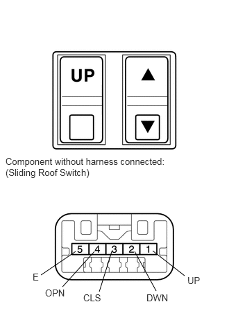
B167041E07
1.135,3.781 0.615,4.135 false 1.417,3.781 0.938,4.313 false 2.021,3.781 2.344,4.375 false 2.292,3.771 2.771,4.146 false 1.677,3.781 1.49,4.385 false 0.083,2.344 2.552,2.677 2.469,0.333 10 false Component without harness connected: (Sliding Roof Switch) 2.813,4.135 3.042,4.313 0.229,0.177 10 false UP 2.198,4.396 2.635,4.563 0.438,0.167 10 false DWN 1.25,4.396 1.771,4.583 0.521,0.188 10 false CLS 0.677,4.323 1.104,4.479 0.427,0.156 10 false OPN 0.49,4.083 0.854,4.24 0.365,0.156 10 false E


b.

Measure the resistance according to the value(s) in the table below.

Standard resistance:
Tester Connection Switch Condition Specified Condition
1 (UP) - 5 (E) TILT switch is pressed to up Below 1 Ω
1 (UP) - 5 (E) TILT switch is not pressed to up 10 kΩ or higher
2 (DWN) - 5 (E) TILT switch is pressed to down Below 1 Ω
2 (DWN) - 5 (E) TILT switch is not pressed to down 10 kΩ or higher
4 (OPN) - 5 (E) SLIDE switch is pressed to open Below 1 Ω
4 (OPN) - 5 (E) SLIDE switch is not pressed to open 10 kΩ or higher
3 (CLS) - 5 (E) SLIDE switch is pressed to close Below 1 Ω
3 (CLS) - 5 (E) SLIDE switch is not pressed to close 10 kΩ or higher


OK

5.INSPECT ROOF CONSOLE BOX ASSEMBLY

NG

5.INSPECT ROOF CONSOLE BOX ASSEMBLY
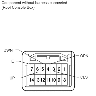
E146741E05
0.054,0.007 2.606,0.350 2.552,0.343 10 Component without harness connected: (Roof Console Box) 0.342,2.706 0.575,2.882 0.232,0.177 10 UP 0.405,2.104 0.540,2.260 0.135,0.156 10 E 0.129,1.722 0.537,1.878 0.408,0.156 10 DWN 2.875,2.68 3.204,2.849 0.330,0.170 10 CLS 2.868,1.915 3.198,2.085 0.330,0.170 10 OPN 1.086,2.302 0.687,2.193 0.687,2.193 0.571,2.193 false 1.361,2.577 0.747,2.791 0.747,2.791 0.599,2.791 false 1.756,2.302 2.732,1.992 2.732,1.992 2.827,1.992 false 1.945,2.559 2.755,2.766 2.755,2.766 2.832,2.766 false 1.535,2.276 0.67,1.783 0.67,1.783 0.556,1.783 false

a.

Remove the roof console box with sliding roof switch (see page Vehicle Interior>INTERIOR>OVERHEAD CONSOLE BOX>REMOVAL).


b.

Measure the resistance according to the value(s) in the table below.

Standard resistance:
Tester Connection Switch Condition Specified Condition
6 (UP) - 7 (E) TILT switch is pressed to up Below 1 Ω
6 (UP) - 7 (E) TILT switch is not pressed to up 10 kΩ or higher
5 (DWN) - 7 (E) TILT switch is pressed to down Below 1 Ω
5 (DWN) - 7 (E) TILT switch is not pressed to down 10 kΩ or higher
4 (OPN) - 7 (E) SLIDE switch is pressed to open Below 1 Ω
4 (OPN) - 7 (E) SLIDE switch is not pressed to open 10 kΩ or higher
3 (CLS) - 7 (E) SLIDE switch is pressed to close Below 1 Ω
3 (CLS) - 7 (E) SLIDE switch is not pressed to close 10 kΩ or higher


OK

REPLACE SLIDING ROOF DRIVE GEAR SUB-ASSEMBLY

NG

REPLACE ROOF CONSOLE BOX ASSEMBLY