Home › Engine / Hybrid System › HYBRID / BATTERY CONTROL › WATER PUMP WITH MOTOR › from 2021.07
RM3700E _51 Engine / Hybrid System _093506 HYBRID / BATTERY CONTROL _0441191 WATER PUMP WITH MOTOR A

HYBRID / BATTERY CONTROL  WATER PUMP WITH MOTOR  INSTALLATION  


CAUTION / NOTICE / HINT
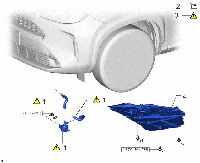
COMPONENTS (INSTALLATION)
A472781N02
4.354,5.271 5.354,5.438 1,0.167 0.531,3.979 1.531,4.146 1,0.167 6.51,0.219 6.844,0.219 false 6.51,0.552 6.844,0.552 true 6.156,3.833 6.323,3.417 6.323,3.417 6.49,3.417 false 2.698,4.167 3.135,3.542 3.135,3.542 3.302,3.542 false 1.667,3.583 2.333,3.583 false 2.25,4.708 2.25,5.125 false 5.354,5.354 5.688,5.354 false 1.531,4.063 1.865,4.063 false 3.667,3.427 3.948,3.781 0.281,0.354 18 false 1 2.271,5.135 2.552,5.49 0.281,0.354 18 false 1 1.51,3.49 1.792,3.844 0.281,0.354 18 false 1 6.313,0.073 6.594,0.427 0.281,0.354 18 false 2 6.25,0.396 6.49,0.677 0.24,0.281 18 true 3 6.542,3.302 6.823,3.656 0.281,0.354 18 false 4 4.99,4.948 5.302,5.146 0.313,0.198 10 false x4 5.792,5.333 6.104,5.531 0.313,0.198 10 false x4 6.469,5.042 6.781,5.24 0.313,0.198 10 false x9 4.396,5.271 5.375,5.427 0.979,0.156 8 false 5.0 (51, 44 in.*lbf) 0.573,3.979 1.552,4.135 0.979,0.156 8 false 7.0 (71, 62 in.*lbf) 1.906,4.125 2.219,4.323 0.313,0.198 10 false x2

Procedure Part Name Code
Z101186

Z101188

Z101187

1 INVERTER WATER PUMP ASSEMBLY G9040 (Click here) - -
2 ADD COOLANT (for Inverter) - - (Click here) -
3 INSPECT FOR COOLANT LEAK (for Inverter) - (Click here) - -
4 CENTER ENGINE UNDER COVER 51451A - - -

V100146

N*m (kgf*cm, ft.*lbf): Specified torque - -

PROCEDURE

Hide G9040 1.INSTALL INVERTER WATER PUMP ASSEMBLY
a.
A460035C01
1.531,1.292 1.708,1.125 true 1.51,0.667 1.729,1.01 true 6.531,0.531 6.75,0.875 true 6.844,0.875 6.969,1.24 true 0.167,0.438 0.479,0.635 0.313,0.198 10 false *2 0.635,0.417 0.948,0.615 0.313,0.198 10 false *e 1.021,0.729 1.333,0.927 0.313,0.198 10 false *f 1.219,0.927 1.531,1.125 0.313,0.198 10 false *d 1.354,1.271 1.667,1.469 0.313,0.198 10 false *c 0.729,1.188 1.104,1.385 0.375,0.198 10 false 135° 1.365,0.521 1.677,0.719 0.313,0.198 10 false *b 5.146,0.427 5.458,0.625 0.313,0.198 10 false *1 5.75,1.156 6.125,1.354 0.375,0.198 10 false 120° 5.427,1.26 5.74,1.458 0.313,0.198 10 false *g 6.125,0.771 6.438,0.969 0.313,0.198 10 false *f 6.385,0.406 6.698,0.604 0.313,0.198 10 false *a 6.896,1.26 7.125,1.448 0.229,0.188 10 false *c 6.646,1.271 6.875,1.458 0.229,0.188 10 false *d 0.438,0.052 0.635,0.344 0.198,0.292 18 false i
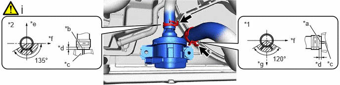
*1 Outlet No. 1 Hybrid Water Pump Hose *2 Inlet Hybrid Water Pump Hose
*a Alignment Mark (White) *b Alignment Mark (Pink or Red)
*c Rib *d 2 to 5 mm (0.0787 to 0.197 in.)
*e Front of Vehicle *f RH Side
*g Down - -


i.

Connect the outlet No. 1 hybrid water pump hose and inlet hybrid water pump hose to the inverter water pump assembly and slide the 2 clips to secure them.

NOTICE:

To prevent foreign matter from entering the inverter water pump assembly and inverter cooling system, do not remove the pieces of cloth from the pipes and disconnected hoses until installation.


HINT:
·

Make sure to align the alignment marks of the hoses with the ribs of the inverter water pump assembly.

·

Make sure that the clips are positioned as shown in the illustration.


b.
A462849N01
0.229,0.042 0.51,0.396 0.281,0.354 18 false i 4.01,0.073 4.24,0.396 0.229,0.323 18 true ii 0.448,1.99 0.698,2.292 0.25,0.302 18 true iii

i.

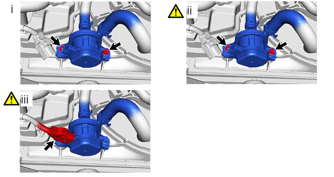
Temporarily install the inverter water pump assembly to the fan shroud assembly with the 2 bolts.


ii.

Fully tighten the 2 bolts.

Torque:
7.0 N*m (71 kgf*cm, 62 in.*lbf)

NOTICE:

As overtightening the bolts may damage the fan shroud assembly, make sure to use a torque wrench.


iii.

Connect the inverter water pump assembly connector.

NOTICE:

If a dustproof cap is installed to the inverter water pump assembly connector, do not remove it until the connector is to be connected.


Hide 2.ADD COOLANT (for Inverter)

Hide 51410 4.INSTALL NO. 1 ENGINE UNDER COVER ASSEMBLY