Home › Engine / Hybrid System › M15A-FKS (INTAKE / EXHAUST) › EXHAUST MANIFOLD › from 2021.07
RM3700E _51 Engine / Hybrid System _093769 M15A-FKS INTAKE / EXHAUST _0442049 EXHAUST MANIFOLD A

M15A-FKS INTAKE / EXHAUST  EXHAUST MANIFOLD  INSTALLATION  


CAUTION / NOTICE / HINT
COMPONENTS (INSTALLATION)
A490447N03
0.125,0.083 5.125,2.083 5,2 0.302,0.542 0.969,0.708 0.667,0.167 1.667,0.75 2.333,0.917 0.667,0.167 6.156,0.719 6.823,0.885 0.667,0.167 4.417,0.333 5.083,0.5 0.667,0.167 3.75,1.167 4.583,1.5 0.833,0.333 5.417,2.667 6.417,2.833 1,0.167 2.75,2.25 3.5,2.417 0.75,0.167 0.917,2.917 1.667,3.083 0.75,0.167 0.917,2.25 1.667,2.417 0.75,0.167 0.208,3.875 0.875,4.042 0.667,0.167 0.917,1.75 1.354,1.75 false 0.958,4.583 1.292,4.583 false 6.448,3.219 6.781,3.219 false 3.99,4.906 4.417,5.25 4.417,5.25 4.583,5.25 false 3.5,2.333 3.667,2.333 3.667,2.333 3.792,2.458 false 5.583,1.573 6,1.333 6,1.333 6.167,1.333 false 4.604,2.875 4.938,2.875 false 3.979,3.323 4.156,3.417 4.156,3.417 4.323,3.417 false 2.5,3.25 2.5,2.948 false 3.125,0.5 3.458,0.5 false 0.75,2.667 1.083,2.667 false 2.354,4.083 2.688,4.083 false 2.479,1.792 2.813,1.792 false 5.396,0.885 5.5,1.073 5.5,1.073 5.667,1.073 false 1.583,2.083 1.583,0.083 false 0.969,0.625 1.219,0.625 false 2.333,0.833 2.5,0.833 2.5,0.833 2.698,0.667 false 4.292,0.417 4.417,0.417 false 4.156,1.156 4.156,0.854 false 6.417,2.75 6.75,2.75 false 0.635,3 0.917,3 false 0.531,2.458 0.75,2.333 0.75,2.333 0.917,2.333 false 0.875,3.958 1.156,3.958 false 6.49,0.24 6.823,0.24 false 5.906,0.802 6.146,0.802 false 3.854,2.5 4.167,2.698 0.313,0.198 10 false x6 6.25,3.948 6.563,4.146 0.313,0.198 10 false x2 6.042,4.417 6.354,4.615 0.313,0.198 10 false x2 1.792,5.396 2.104,5.594 0.313,0.198 10 false x2 2.375,5.594 2.688,5.792 0.313,0.198 10 false x2 0.771,4.521 1.083,4.719 0.313,0.198 10 false ● 6.865,3.156 7.104,3.406 0.24,0.25 10 false ● 2.594,2.229 2.833,2.479 0.24,0.25 10 false ● 2.385,3.25 2.625,3.5 0.24,0.25 10 false ● 1.344,0.563 1.656,0.76 0.313,0.198 10 false x3 4.979,2.708 5.292,3.042 0.313,0.333 18 false 9 5.729,0.958 6.042,1.292 0.313,0.333 18 false 8 2.271,1.625 2.583,1.958 0.313,0.333 18 false 5 3.521,0.354 3.833,0.688 0.313,0.333 18 false 7 6.198,1.177 6.708,1.542 0.51,0.365 18 false 10 3.521,1.177 3.833,1.51 0.313,0.333 18 false 6 4.938,5.083 5.25,5.417 0.313,0.333 18 false 11 4.552,3.24 4.948,3.573 0.396,0.333 18 false 3 2.531,3.229 2.979,3.583 0.448,0.354 18 false 2 0.708,1.583 1.021,1.917 0.313,0.333 18 false 5 2.823,0.615 3.135,0.813 0.313,0.198 10 false x2 1.323,2.49 1.771,2.844 0.448,0.354 18 false 4 2.75,3.906 3.198,4.26 0.448,0.354 18 false 1 0.208,0.135 0.583,0.375 0.375,0.24 12 false *A 1.625,0.135 2,0.375 0.375,0.24 12 false *B 1.26,3.896 1.573,4.094 0.313,0.198 10 false x3 0.344,0.542 1.698,0.698 1.354,0.156 8 false 10 (102, 7) 1.729,0.75 3.083,0.906 1.354,0.156 8 false 10 (102, 7) 6.188,0.719 7.156,1.031 0.969,0.313 8 false 13 (133, 10) 4.479,0.344 5.833,0.5 1.354,0.156 8 false 10 (102, 7) 3.771,1.177 5.24,1.333 1.469,0.156 8 false 30 (306, 22) 3.771,1.333 5.24,1.49 1.469,0.156 8 false 26.3 (268, 19)* 5.448,2.667 6.802,2.823 1.354,0.156 8 false 5.0 (51, 44 in.*lbf) 2.802,2.25 4.156,2.406 1.354,0.156 8 false 26 (265, 19) 0.979,2.917 2.333,3.073 1.354,0.156 8 false 43 (438, 32) 0.979,2.25 2.333,2.406 1.354,0.156 8 false 43 (438, 32) 0.25,3.875 1.604,4.031 1.354,0.156 8 false 10 (102, 7) 6.146,0.104 6.771,0.594 0.625,0.49 18 false 12

Procedure Part Name Code
Z101186

Z101188

Z101187

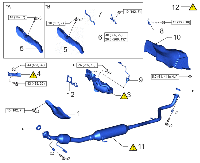
1 NO. 2 EXHAUST MANIFOLD HEAT INSULATOR 17168 - - -
2 EXHAUST MANIFOLD TO HEAD GASKET 17173 - - -
3 EXHAUST MANIFOLD 17141 (Click here) - -
4 MANIFOLD STAY 17118 (Click here) - -
5 NO. 1 EXHAUST MANIFOLD HEAT INSULATOR 17167 - - -
6 NO. 1 VACUUM PIPE 25733A - - -
7 VACUUM TRANSMITTING HOSE ASSEMBLY 25760 - - -
8 WIRE HARNESS CLAMP BRACKET - - - -
9 AIR FUEL RATIO SENSOR 89467B - - -
10 NO. 1 FRONT FLOOR HEAT INSULATOR 58151 - - -
11 FRONT EXHAUST PIPE ASSEMBLY 17410 (Click here) - -
12 INSPECT FOR EXHAUST GAS LEAK - (Click here) - -

*A w/o Differential Pressure Sensor *B w/ Differential Pressure Sensor
V100146

N*m (kgf*cm, ft.*lbf): Specified torque ● Non-reusable part

A490425N03
0.25,0.083 7,1.708 6.75,1.625 0.344,1.417 1.094,1.583 0.75,0.167 1.583,1.208 2.552,1.375 0.969,0.167 4.5,1.5 5.5,1.667 1,0.167 5.833,1.5 6.833,1.667 1,0.167 3.646,0.646 3.917,0.646 false 6.177,0.635 6.656,0.635 false 0.938,0.729 1.417,0.729 false 4.333,1.708 4.333,0.083 false 1.094,1.5 1.344,1.5 false 2.563,1.292 2.813,1.292 false 5.333,1.5 5.333,1.354 false 6.552,1.5 6.552,1.26 false 3.917,0.49 4.375,0.917 0.458,0.427 18 false 14 5.417,1.229 5.729,1.427 0.313,0.198 10 false x2 2.948,1.208 3.26,1.406 0.313,0.198 10 false x4 6.667,0.458 7.073,0.833 0.406,0.375 18 false 14 1.49,0.563 2.021,0.948 0.531,0.385 18 false 13 1.458,1.406 1.771,1.604 0.313,0.198 10 false x2 6.635,1.135 6.948,1.333 0.313,0.198 10 false x2 0.333,0.188 0.667,0.427 0.333,0.24 12 false *A 4.375,0.177 4.708,0.417 0.333,0.24 12 false *B 0.385,1.417 1.854,1.573 1.469,0.156 8 false 22 (224, 16) 1.615,1.208 4.063,1.365 2.448,0.156 8 false 5.0 (51, 44 in.*lbf) 4.552,1.5 7,1.656 2.448,0.156 8 false 5.0 (51, 44 in.*lbf) 5.885,1.5 7.125,1.667 1.24,0.167 8 false 5.0 (51, 44 in.*lbf)

Procedure Part Name Code
Z101186

Z101188

Z101187

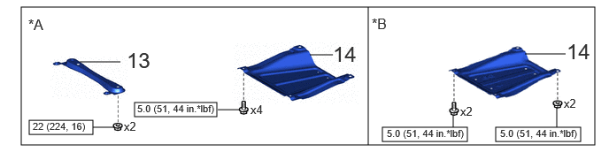
13 CENTER NO. 1 FLOOR BRACE 57543C - - -
14 CENTER NO. 4 ENGINE UNDER COVER 51447D - - -

*A for TMMF Made *B for TMC Made
V100146

N*m (kgf*cm, ft.*lbf): Specified torque - -

PROCEDURE

Hide 17168 1.INSTALL NO. 2 EXHAUST MANIFOLD HEAT INSULATOR

Torque:
10 N*m (102 kgf*cm, 7 ft.*lbf)

Hide 17173 2.INSTALL EXHAUST MANIFOLD TO HEAD GASKET

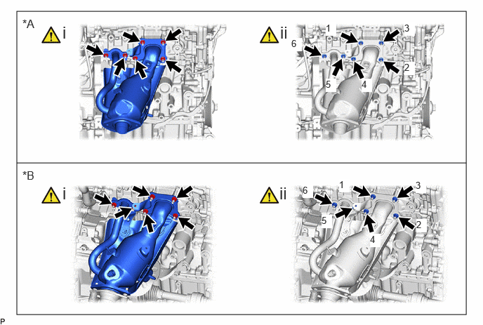
Hide 17141 3.INSTALL EXHAUST MANIFOLD

a.
A490429C01
0.25,0.167 6.917,4.667 6.667,4.5 0.25,2.417 6.917,2.417 false 0.333,0.25 0.646,0.583 0.313,0.333 12 false *A 0.333,2.5 0.667,2.823 0.333,0.323 12 false *B 0.927,0.333 1.208,0.688 0.281,0.354 18 false i 0.927,2.719 1.208,3.073 0.281,0.354 18 false i 4.156,0.333 4.438,0.688 0.281,0.354 18 false ii 4.146,2.719 4.427,3.073 0.281,0.354 18 false ii 4.833,0.333 4.99,0.531 0.156,0.198 10 true 1 6,0.917 6.156,1.115 0.156,0.198 10 true 2 6,0.333 6.156,0.531 0.156,0.198 10 true 3 5.365,1.167 5.521,1.365 0.156,0.198 10 true 4 4.833,1.167 4.99,1.365 0.156,0.198 10 true 5 4.323,0.563 4.479,0.76 0.156,0.198 10 true 6 5.031,2.656 5.188,2.854 0.156,0.198 10 true 1 6.167,2.667 6.323,2.865 0.156,0.198 10 true 3 6.177,3.25 6.333,3.448 0.156,0.198 10 true 2 5.49,3.469 5.646,3.667 0.156,0.198 10 true 4 4.771,3.188 4.927,3.385 0.156,0.198 10 true 5 4.49,2.74 4.646,2.938 0.156,0.198 10 true 6
*A w/o Differential Pressure Sensor *B w/ Differential Pressure Sensor


i.

Install a new exhaust manifold to head gasket to the cylinder head sub-assembly.


ii.

Temporarily install the exhaust manifold to the cylinder head sub-assembly with 6 new nuts.


iii.

Tighten the 6 nuts in the order shown in the illustration.

Torque:
26 N*m (265 kgf*cm, 19 ft.*lbf)


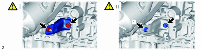
Hide 17118 4.INSTALL MANIFOLD STAY

a.
A461352N01
6.24,0.542 6.385,0.698 0.146,0.156 10 true 1 4.708,0.719 4.854,0.875 0.146,0.156 10 true 2 0.667,0.094 0.948,0.448 0.281,0.354 18 false i 4.115,0.083 4.313,0.385 0.198,0.302 18 true ii

i.

Temporarily install the manifold stay to the exhaust manifold and cylinder block sub-assembly with the bolt and nut.


ii.

Tighten the bolt and nut in the order shown in the illustration.

Torque:
43 N*m (438 kgf*cm, 32 ft.*lbf)


Hide 17167 5.INSTALL NO. 1 EXHAUST MANIFOLD HEAT INSULATOR

Torque:
10 N*m (102 kgf*cm, 7 ft.*lbf)

Hide 25733A 6.INSTALL NO. 1 VACUUM PIPE (w/ Differential Pressure Sensor)
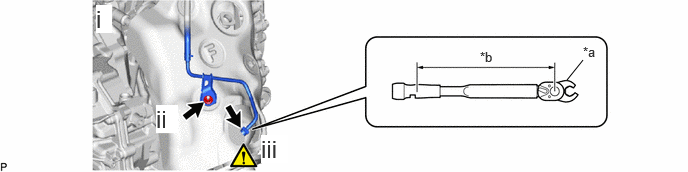
a.
A490448C01
5.906,0.833 6.073,0.625 false 6.073,0.458 6.385,0.615 0.313,0.156 10 false *a 5,0.51 5.313,0.667 0.313,0.156 10 false *b 1,0.052 1.167,0.344 0.167,0.292 18 true i 1.625,1.094 1.854,1.385 0.229,0.292 18 true ii 2.719,1.406 3,1.698 0.281,0.292 18 true iii
*a 14 mm Union Nut Wrench *b Torque Wrench Fulcrum Length


i.

Temporarily install a new No. 1 vacuum transmitting pipe sub-assembly to the exhaust manifold with the nut.


ii.

Tighten the nut.

Torque:
10 N*m (102 kgf*cm, 7 ft.*lbf)


iii.

Using a 14 mm union nut wrench, tighten the No. 1 vacuum transmitting pipe sub-assembly.

Torque:
30 N*m (306 kgf*cm, 22 ft.*lbf)

HINT:
·

Calculate the torque wrench reading when changing the fulcrum length of the torque wrench.

Click hereGeneral>INTRODUCTION>REPAIR INSTRUCTION>PRECAUTION

·

When using a 14 mm union nut wrench (fulcrum length of 25 mm (0.984 in.)) + torque wrench (fulcrum length of 180 mm (7.09 in.)): 26.3 N*m (268 kgf*cm, 19 ft.*lbf).


Hide 25760 7.INSTALL VACUUM TRANSMITTING HOSE ASSEMBLY (w/ Differential Pressure Sensor)

Hide 8.INSTALL WIRE HARNESS CLAMP BRACKET

Torque:
13 N*m (133 kgf*cm, 10 ft.*lbf)

Hide 58151 10.INSTALL NO. 1 FRONT FLOOR HEAT INSULATOR

Torque:
5.0 N*m (51 kgf*cm, 44 in.*lbf)

Hide 17410 11.INSTALL FRONT EXHAUST PIPE ASSEMBLY
a.
A450934C06
1.031,1.448 1.031,1.115 false 2.01,1.5 1.76,1.229 true 4.469,1.438 4.469,1.104 false 5.083,1.573 5.083,1.24 false 0.969,1.49 1.281,1.688 0.313,0.198 10 false *1 2.052,1.469 2.365,1.667 0.313,0.198 10 false *2 4.396,1.469 4.708,1.667 0.313,0.198 10 false *1 5.01,1.604 5.323,1.771 0.313,0.167 10 false *2 0.5,0.167 0.781,0.521 0.281,0.354 18 false i 4.26,0.167 4.542,0.521 0.281,0.354 18 false ii
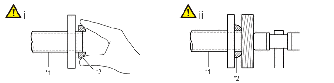
*1 Exhaust Manifold or Front Exhaust Pipe Assembly *2 Exhaust Pipe Gasket


i.

Temporarily install 2 new exhaust pipe gaskets to the exhaust manifold and front exhaust pipe assembly.


ii.

Using a plastic hammer and wooden block, tap in each exhaust pipe gasket until its surface is flush with the exhaust manifold and front exhaust pipe assembly.

NOTICE:
·

Be sure to install the exhaust pipe gasket in the correct direction.

·

Do not reuse the exhaust pipe gaskets.

·

Do not damage the exhaust pipe gaskets.

·

Do not push in the exhaust pipe gaskets by using the exhaust pipes when connecting them.


b.
A472706C02
2.042,0.833 2.188,1.052 false 5.938,0.823 6.083,1.042 false 2.188,1.188 2.125,1.719 false 6.063,1.177 5.99,1.688 false 2.844,1.24 2.875,1.76 true 6.719,1.229 6.75,1.75 true 1.969,0.656 2.281,0.854 0.313,0.198 10 false *1 5.792,0.729 6.104,0.927 0.313,0.198 10 false *4 2.031,1.729 2.344,1.927 0.313,0.198 10 false *2 5.927,1.698 6.24,1.896 0.313,0.198 10 false *2 1.906,1.375 2.219,1.573 0.313,0.198 10 false *a 5.854,1.385 6.167,1.583 0.313,0.198 10 false *b 2.792,1.781 3.104,1.979 0.313,0.198 10 false *3 6.698,1.76 7.01,1.958 0.313,0.198 10 false *3 0.656,1.073 0.938,1.427 0.281,0.354 18 false i 3.979,1.396 4.24,1.698 0.26,0.302 18 true ii 2.25,1.719 2.531,2.073 0.281,0.354 18 false iii 2.177,3.094 2.49,3.375 0.313,0.281 18 true vii 1.906,2.469 2.208,2.771 0.302,0.302 18 true viii 5.333,0.406 5.615,0.76 0.281,0.354 18 false vi 1.406,0.49 1.708,0.792 0.302,0.302 18 false iv 6.156,1.635 6.438,1.99 0.281,0.354 18 false v
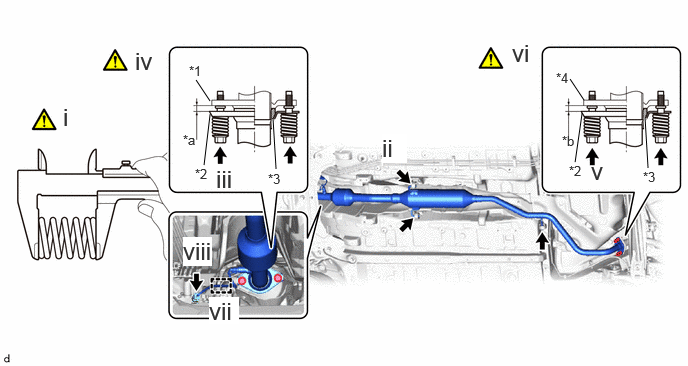
*1 Exhaust Manifold *2 Front Exhaust Pipe Assembly
*3 Exhaust Pipe Gasket *4 Tail Exhaust Pipe Assembly
*a Space between Flanges: 8.5 mm (0.335 in.) *b Space between Flanges: 6.5 mm (0.256 in.)


i.

Using a vernier caliper, measure the free length of the compression springs.

Minimum Free Length (Front) 41.5 mm (1.63 in.)
Minimum Free Length (Rear) 38.5 mm (1.52 in.)

1, If the free length is less than the minimum, replace the compression spring.


ii.

Connect the front exhaust pipe assembly to the 3 exhaust pipe supports.


iii.

Install the front exhaust pipe assembly to the exhaust manifold with the 2 compression springs and 2 bolts.

Torque:
43 N*m (438 kgf*cm, 32 ft.*lbf)


iv.

After installation, check that the space between the flanges of the exhaust manifold and front exhaust pipe assembly is consistent front-to-rear and left-to-right.


v.

Install the front exhaust pipe assembly to the tail exhaust pipe assembly with the 2 compression springs and 2 bolts.

Torque:
43 N*m (438 kgf*cm, 32 ft.*lbf)


vi.

After installation, check that the space between the flanges of the front exhaust pipe assembly and tail exhaust pipe assembly is consistent front-to-rear and left-to-right.


vii.

Engage the clamp.


viii.

Connect the No. 2 air fuel ratio sensor connector.


Hide 57543C 13.INSTALL CENTER NO. 1 FLOOR BRACE (for TMMF Made)

Torque:
22 N*m (224 kgf*cm, 16 ft.*lbf)

Hide 51447D 14.INSTALL CENTER NO. 4 ENGINE UNDER COVER