MIRROR (EXT) OUTER REAR VIEW MIRROR(for TMC Made) REASSEMBLY
CAUTION / NOTICE / HINT
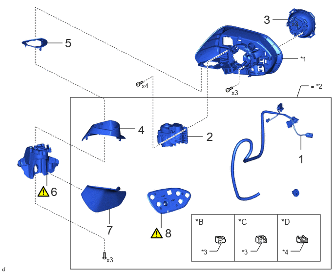
| Procedure | Part Name Code | 
|

|

|
|
|---|---|---|---|---|---|
| 1 | WIRE HARNESS | - | - | - | - |
| 2 | OUTER MIRROR RETRACTOR SUB-ASSEMBLY | - | - | - | - |
| 3 | POWER UNIT ASSEMBLY | - | - | - | - |
| 4 | UPPER BASE COVER | - | - | - | - |
| 5 | BASE SEAL | - | - | - | - |
| 6 | BASE SUB-ASSEMBLY | - | ( ) |
- | - |
| 7 | OUTER MIRROR HOLE COVER | 87948 | - | - | - |
| 8 | GASKET | - | ()
|
- | - |
| *A | w/o Panoramic View Monitor System, w/o Mirror Heater | *B | w/o Panoramic View Monitor System, w/ Mirror Heater |
| *C | w/ Panoramic View Monitor System | - | - |
| *1 | BODY | *2 | OUTER MIRROR RETRACTOR |
| *3 | HOLDER | *4 | CONNECTOR |
| ● | Non-reusable part | - | - |
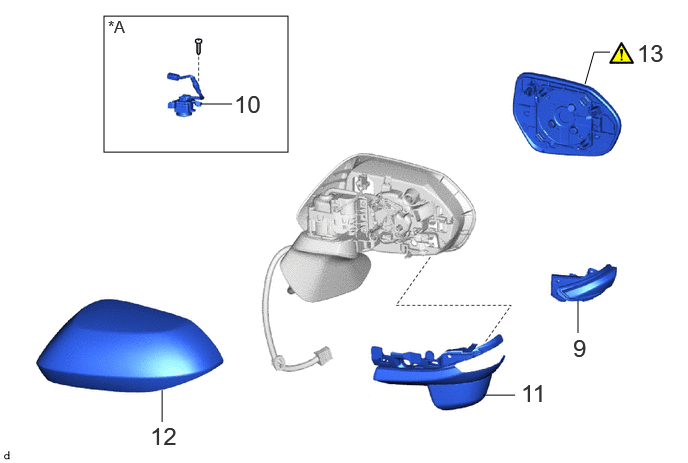
| Procedure | Part Name Code |
|
|
|
|
|---|---|---|---|---|---|
| 9 | SIDE TURN SIGNAL LIGHT ASSEMBLY | 81740 | - | - | - |
| 10 | SIDE TELEVISION CAMERA ASSEMBLY | 86790F | - | - | - |
| 11 | OUTER MIRROR LOWER COVER | - | - | - | - |
| 12 | OUTER MIRROR COVER | 87945 | - | - | - |
| 13 | OUTER MIRROR | 87961 | ()
|
- | - |
| *A | w/ Panoramic View Monitor System | - | - |
CAUTION / NOTICE / HINT
- HINT:
- ·
Use the same procedure for the RH side and LH side.
·The following procedure is for the LH side.
PROCEDURE

 1.INSTALL WIRE HARNESS
2.INSTALL OUTER MIRROR RETRACTOR SUB-ASSEMBLY
3.INSTALL POWER UNIT ASSEMBLY
4.INSTALL UPPER BASE COVER
5.INSTALL BASE SEAL
6.INSTALL BASE SUB-ASSEMBLY
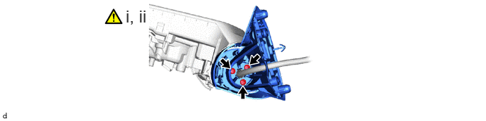
Pass the wire harness through the base sub-assembly to temporarily install the base sub-assembly with base seal and upper base cover.
Using a T25 "TORX" socket wrench, install the base sub-assembly with the 3 new screws.
- NOTICE:
- ·
Check that the wire harness is not caught.
·Do not damage the screw coating.
·Securely tighten the screws so that they will not come loose.
87948
7.INSTALL OUTER MIRROR HOLE COVER
8.INSTALL GASKET
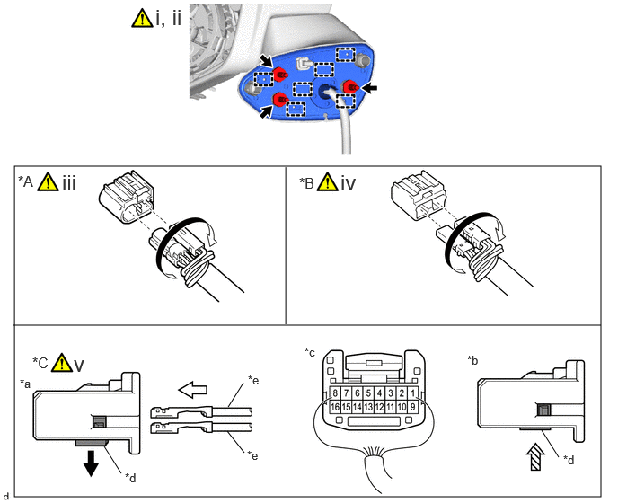
| *A | w/o Panoramic View Monitor System, w/o Mirror Heater | *B | w/o Panoramic View Monitor System, w/ Mirror Heater |
| *C | w/ Panoramic View Monitor System | - | - |
| *a | Unlock Position | *b | Lock Position |
| *c | Rear view of connector | *d | Retainer |
| *e | Terminal | - | - |
Pass the wire harness through a new gasket, engage the guides to install the gasket.
- NOTICE:
-
Do not make gaps between the base and gasket.
Install the 3 stud bolts.
w/o Panoramic View Monitor System, w/o Mirror Heater:
1. Rotate the connector and twist the longer wire harness as shown in the illustration.
2. Connect each connector to a new adapter.
w/o Panoramic View Monitor System, w/ Mirror Heater:
1. Rotate the connector and twist the longer wire harness as shown in the illustration.
2. Connect each connector to a new adapter.
w/ Panoramic View Monitor System:
1. Pull the retainer and release the lock of connector.
2. While referring to the chart below, insert the terminals of the wire harness into the back of a new connector until they lock.
- NOTICE:
- ·
When inserting the terminals of the wire harness, compare the new connector with the connector that was cut off during removal and make sure that the arrangement of the wire colors of the terminals is the same as before.
·If the insertion position of the terminals is mistaken, the vehicle side control system may be damaged.
·Check that the terminals are securely locked and cannot be removed.
| 1 | 2 | 3 | 4 | 5 | 6 | 7 | 8 |
| Purple | - | Sky blue | - | Orange | Yellow - Black | Black - Green | Black - Red |
| 9 | 10 | 11 | 12 | 13 | 14 | 15 | 16 |
| Brown | Red | Light Green | - | Gray | White - Black | White | Pink |
3. Push the retainer and lock the connector.
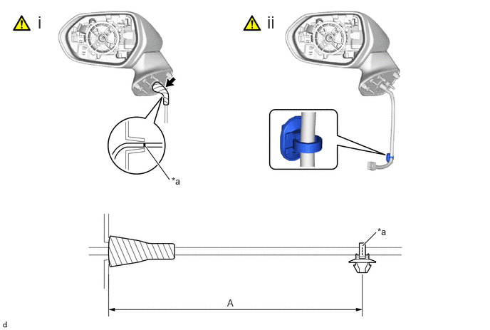
| *a | Mark | - | - |
Install the vinyl tape as shown in the illustration.
While referring to the chart below, install a new clip.
| Area | Measurement | Area | Measurement |
|---|---|---|---|
| A | 382 to 392 mm (15.0 to 15.4 in.) | - | - |
81740
9.INSTALL SIDE TURN SIGNAL LIGHT ASSEMBLY
86790F
10.INSTALL SIDE TELEVISION CAMERA ASSEMBLY
11.INSTALL OUTER MIRROR LOWER COVER
87945
12.INSTALL OUTER MIRROR COVER
87961
13.INSTALL OUTER MIRROR
|
|
Click here()
|