EC6D MANUAL TRANSMISSION / TRANSAXLE MANUAL TRANSAXLE SYSTEM P080512 Clutch Position Sensor "A"Circuit Short to Battery P080514 Clutch Position Sensor "A"Circuit Short to Ground or Open
DESCRIPTION
The clutch pedal stroke sensor assembly is installed to the clutch pedal support sub-assembly. It detects the clutch pedal position and sends signals to the ECM.
| DTC No. | Detection Item | DTC Detection Condition | Trouble Area | MIL | Memory | DTC Output from | Priority | Note |
|---|---|---|---|---|---|---|---|---|
| P080512 | Clutch Position Sensor "A"Circuit Short to Battery | Clutch pedal stroke sensor assembly signal voltage is 4.7 V or more for 0.5 seconds or more (1-trip detection logic) | ·
Clutch pedal stroke sensor assembly ·
Short to +B in clutch pedal stroke sensor assembly circuit ·
ECM |
Does not come on | DTC stored | Engine | A | SAE Code:
P0808 |
| P080514 | Clutch Position Sensor "A"Circuit Short to Ground or Open | Clutch pedal stroke sensor assembly signal voltage is 0.3 V or less for 0.5 seconds or more (1-trip detection logic) | ·
Clutch pedal stroke sensor assembly ·
Open or short to ground in clutch pedal stroke sensor assembly circuit ·
ECM |
Does not come on | DTC stored | Engine | A | SAE Code:
P0807 |
CONFIRMATION DRIVING PATTERN
- HINT:
-
After repairs have been completed, clear the DTCs and then check that the vehicle has returned to normal by performing the following All Readiness check procedure.
Connect the GTS to the DLC3.
Turn the ignition switch to ON and turn the GTS on.
Clear the DTCs (even if no DTCs are stored, perform the clear DTC procedure).
Turn the ignition switch off and wait for 3 minutes or more.
Turn the ignition switch to ON and turn the GTS on.
Wait for 5 seconds or more with the ignition switch ON.
Enter the following menus: Powertrain / Engine / Utility / All Readiness.
Input the DTC: P080512 or P080514.
Check the DTC judgment result.
| GTS Display | Description |
|---|---|
| NORMAL | ·
DTC judgment completed ·
System normal |
| ABNORMAL | ·
DTC judgment completed ·
System abnormal |
| INCOMPLETE | ·
DTC judgment not completed ·
Perform driving pattern after confirming DTC enabling conditions |
| N/A | ·
Unable to perform DTC judgment ·
Number of DTCs which do not fulfill DTC preconditions has reached ECU memory limit |
- HINT:
- ·
If the judgment result shows NORMAL, the system is normal.
·If the judgment result shows ABNORMAL, the system has a malfunction.
·If the judgment result shows INCOMPLETE or N/A, perform the Confirmation Driving Pattern and check the DTC judgment result again.
WIRING DIAGRAM
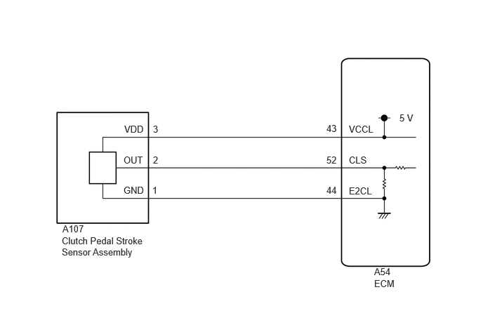
PROCEDURE
Enter the following menus:
According to the display on the GTS, read the Data List.
- Powertrain > Engine > Data List
-
Tester Display Measurement Item Range Normal Condition Diagnostic Note Clutch Stroke Sensor Voltage Clutch pedal stroke sensor assembly output voltage Min.: 0.000 V
Max.: 4.999 VValue increases: Clutch pedal released → clutch pedal fully depressed -
- Powertrain > Engine > Data List
-
Tester Display Clutch Stroke Sensor Voltage - 50003 372 607
- Standard Voltage:
GTS Display Condition Specified Condition Clutch Stroke Sensor Voltage Clutch pedal fully released 0.5 to 1.1 V Clutch pedal fully depressed 2.6 to 4.5 V
- Result:
Result Proceed to Data List value is normal A Data List value is not normal B
A
B
Pre-procedure1
Disconnect the A107 clutch pedal stroke sensor assembly connector.
Turn the ignition switch to ON.
Procedure1
Measure the voltage according to the value(s) in the table below.
- Standard Voltage:
Tester Connection Switch Condition Specified Condition Click Location & Routing(A107)Location & Routingewd_type=routing;type=c;code=A107
Click Connector(A107)Instrument Panel>Engine Room Main Wire>Clutch Pedal Stroke Sensor Assemblyewd_type=component;type=c;code=A107;pinno=3,1
A107-3 (VDD) - A107-1 (GND) Ignition switch ON 4.5 to 5.5 V
- Result:
Proceed to OK NG
Post-procedure1
Turn the ignition switch off.
Connect A107 the clutch pedal stroke sensor assembly connector.
OK
NG
Pre-procedure1
Disconnect the A54 ECM connector.
Disconnect the A107 clutch pedal stroke sensor assembly connector.
Procedure1
Measure the resistance according to the value(s) in the table below.
- Standard Resistance:
Tester Connection Condition Specified Condition Click Location & Routing(A107,A54)Location & Routingewd_type=routing;type=c,c;code=A107,A54
Click Connector(A107)Instrument Panel>Engine Room Main Wire>Clutch Pedal Stroke Sensor Assemblyewd_type=component;type=c;code=A107;pinno=2
Click Connector(A54)Engine Compartment>Engine Room Main Wire>ECMewd_type=component;type=c;code=A54;pinno=52
A107-2 (OUT) - A54-52 (CLS) Always Below 1 Ω A107-2 (OUT) or A54-52 (CLS) - Body ground Always 10 kΩ or higher
- Result:
Proceed to OK NG
Post-procedure1
Connect the A107 clutch pedal stroke sensor assembly connector.
Connect the A54 ECM connector.
OK
NG
Replace the clutch pedal stroke sensor assembly.
for RHD: Click hereDrivetrain>CLUTCH>CLUTCH STROKE SENSOR (for RHD)>REMOVAL
for LHD: Click hereDrivetrain>CLUTCH>CLUTCH STROKE SENSOR (for LHD)>REMOVAL
- Result:
Proceed to NEXT
NEXT
Clear the DTCs.
- Powertrain > Engine > Clear DTCs
- 50002 372
Turn the ignition switch off and wait for at least 30 seconds.
Enter the following menus:
- Powertrain > Engine > Trouble Codes
- 50001 372
Read the DTCs.
- Result:
Result Proceed to DTCs are not output A DTC P080512 or P080514 is output B
A
B
Pre-procedure1
Disconnect the A54 ECM connector.
Disconnect the A107 clutch pedal stroke sensor assembly connector.
Procedure1
Measure the resistance according to the value(s) in the table below.
- Standard Resistance:
Tester Connection Condition Specified Condition Click Location & Routing(A107,A54)Location & Routingewd_type=routing;type=c,c;code=A107,A54
Click Connector(A107)Instrument Panel>Engine Room Main Wire>Clutch Pedal Stroke Sensor Assemblyewd_type=component;type=c;code=A107;pinno=1,3
Click Connector(A54)Engine Compartment>Engine Room Main Wire>ECMewd_type=component;type=c;code=A54;pinno=44,43
A107-1 (GND) - A54-44 (E2CL) Always Below 1 Ω A107-3 (VDD) - A54-43 (VCCL) Always Below 1 Ω A107-1 (GND) or A54-44 (E2CL) - Body ground Always 10 kΩ or higher A107-3 (VDD) or A54-43 (VCCL) - Body ground Always 10 kΩ or higher
- Result:
Proceed to OK NG
Post-procedure1
Connect the A107 clutch pedal stroke sensor assembly connector.
Connect the A54 ECM connector.
OK
NG