AUDIO / VIDEO AUDIO AND VISUAL SYSTEM(for Radio and Display Type without TAS Type) B15C3 Speaker Output Short
DESCRIPTION
This DTC is stored when a malfunction occurs in the speakers.
| DTC No. | Detection Item | DTC Detection Condition | Trouble Area | DTC Output from | Priority |
|---|---|---|---|---|---|
| B15C3 | Speaker Output Short | A short is detected in the speaker output circuit | ·
Harness or connector ·
Speaker ·
Radio and display receiver assembly*1 ·
Stereo component amplifier assembly*2 ·
Telematics transceiver*3 |
Navigation System | A |
*1: except 8 Speakers
*2: for 8 Speakers
*3: w/ Telematics Transceiver for TMC Made
WIRING DIAGRAM
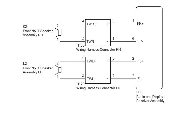
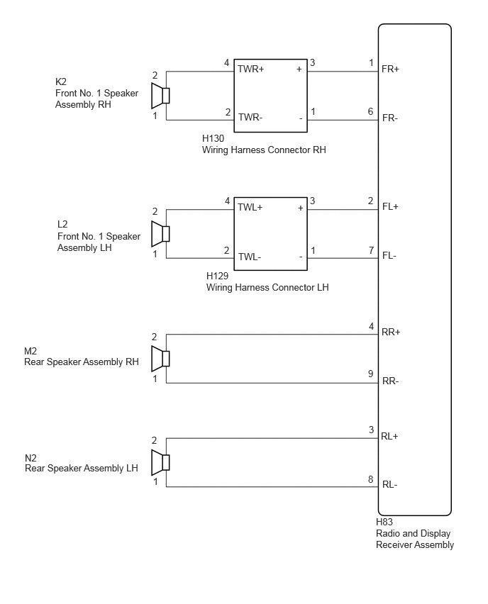
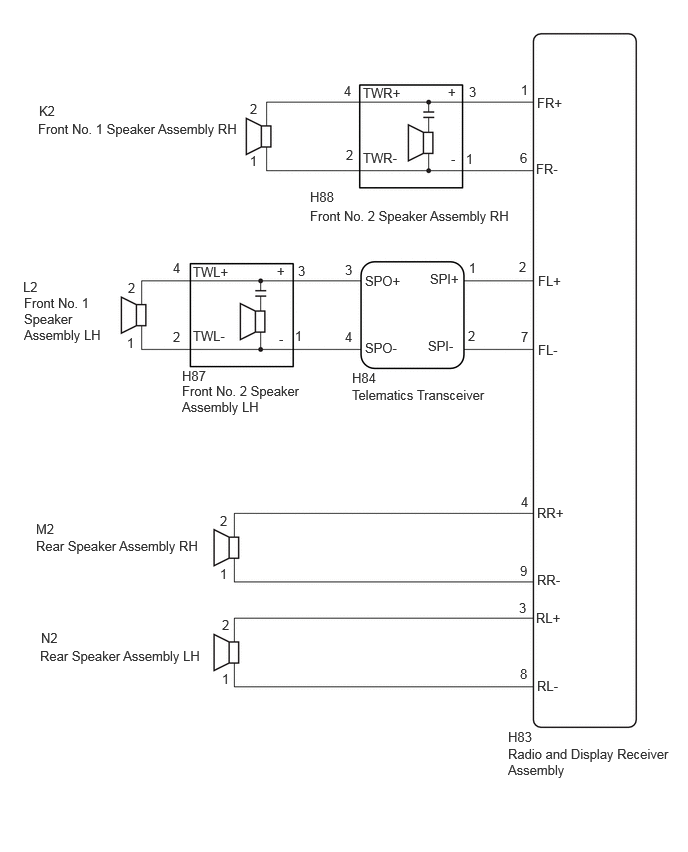
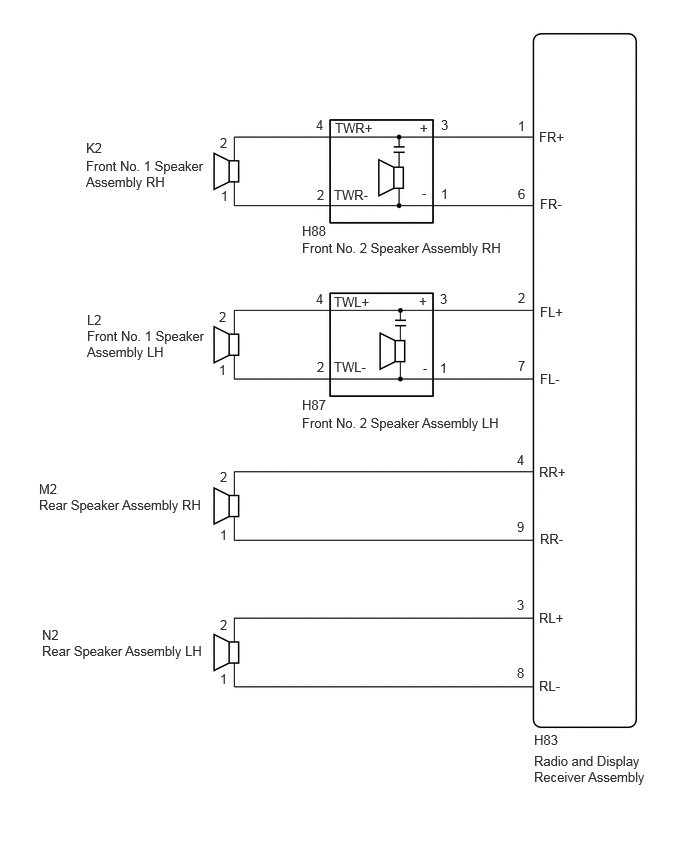
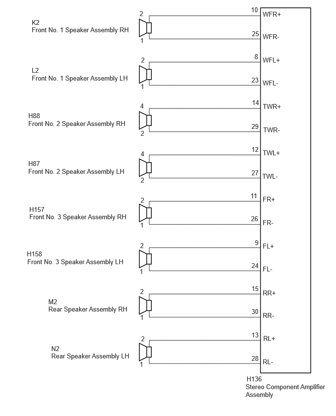
PROCEDURE
Choose the model to be inspected.
- Result:
Result Proceed to for 2 Speakers A for 4 Speakers B for 6 Speakers C for 8 Speakers D
A
B
C
D
Pre-procedure1
Disconnect the H83 radio and display receiver assembly connectors.
Disconnect the H129 and H130 wiring harness connector connectors.
Procedure1
Measure the resistance according to the value(s) in the table below.
- Standard Resistance:
Tester Connection Condition Specified Condition Click Location & Routing(H83,H130,H129)Location & Routingewd_type=routing;type=c,c,c;code=H83,H130,H129
Click Connector(H83)Instrument Panel>Instrument Panel Wire / Speaker Wire>Radio & Display Receiver Assemblyewd_type=component;type=c;code=H83;pinno=1,6,2,7
Click Connector(H130)Instrument Panel>Instrument Panel Wire / Speaker Wire>Wiring Harness Connector RHewd_type=component;type=c;code=H130;pinno=3,1
Click Connector(H129)Instrument Panel>Instrument Panel Wire / Speaker Wire>Wiring Harness Connector LHewd_type=component;type=c;code=H129;pinno=3,1
H83-1 (FR+) or H130-3 (+) - Body ground Always 10 kΩ or higher H83-6 (FR-) or H130-1 (-) - Body ground Always 10 kΩ or higher H83-2 (FL+) or H129-3 (+) - Body ground Always 10 kΩ or higher H83-7 (FL-) or H129-1 (-) - Body ground Always 10 kΩ or higher
- Result:
Proceed to OK NG
Post-procedure1
None
OK
NG
Pre-procedure1
Disconnect the H129 and H130 wiring harness connector connectors.
Disconnect the K2 and L2 front No. 1 speaker assembly connectors.
Procedure1
Measure the resistance according to the value(s) in the table below.
- Standard Resistance:
Tester Connection Condition Specified Condition Click Location & Routing(H130,K2,H129,L2)Location & Routingewd_type=routing;type=c,c,c,c;code=H130,K2,H129,L2
Click Connector(H130)Instrument Panel>Instrument Panel Wire / Speaker Wire>Wiring Harness Connector RHewd_type=component;type=c;code=H130;pinno=4,2
Click Connector(K2)Body>Front Door Wire RH / Television Camera Wire>Front No. 1 Speaker Assembly RHewd_type=component;type=c;code=K2;pinno=2,1
Click Connector(H129)Instrument Panel>Instrument Panel Wire / Speaker Wire>Wiring Harness Connector LHewd_type=component;type=c;code=H129;pinno=4,2
Click Connector(L2)Body>Front Door Wire LH / Television Camera Wire>Front No. 1 Speaker Assembly LHewd_type=component;type=c;code=L2;pinno=2,1
H130-4 (TWR+) or K2-2 - Body ground Always 10 kΩ or higher H130-2 (TWR-) or K2-1 - Body ground Always 10 kΩ or higher H129-4 (TWL+) or L2-2 - Body ground Always 10 kΩ or higher H129-2 (TWL-) or L2-1 - Body ground Always 10 kΩ or higher
- Result:
Proceed to OK NG
Post-procedure1
None
OK
NG
Click hereAudio / Visual / Telematics>AUDIO / VIDEO>FRONT DOOR SPEAKER>INSPECTION
- Result:
Proceed to OK NG
OK
NG
Clear the DTCs.
- Body Electrical > Navigation System > Clear DTCs
- 50002 212
- Result:
Proceed to NEXT
NEXT
Clear the DTCs.
- Body Electrical > Navigation System > Trouble Codes
- 50001 212
- Result:
Result Proceed to DTCs are output A DTCs are not output B
A
B
Pre-procedure1
Disconnect the H83 radio and display receiver assembly connectors.
Disconnect the H129 and H130 wiring harness connector connectors.
Procedure1
Measure the resistance according to the value(s) in the table below.
- Standard Resistance:
Tester Connection Condition Specified Condition Click Location & Routing(H83,H130,H129)Location & Routingewd_type=routing;type=c,c,c;code=H83,H130,H129
Click Connector(H83)Instrument Panel>Instrument Panel Wire / Speaker Wire>Radio & Display Receiver Assemblyewd_type=component;type=c;code=H83;pinno=1,6,2,7
Click Connector(H130)Instrument Panel>Instrument Panel Wire / Speaker Wire>Wiring Harness Connector RHewd_type=component;type=c;code=H130;pinno=3,1
Click Connector(H129)Instrument Panel>Instrument Panel Wire / Speaker Wire>Wiring Harness Connector LHewd_type=component;type=c;code=H129;pinno=3,1
H83-1 (FR+) or H130-3 (+) - Body ground Always 10 kΩ or higher H83-6 (FR-) or H130-1 (-) - Body ground Always 10 kΩ or higher H83-2 (FL+) or H129-3 (+) - Body ground Always 10 kΩ or higher H83-7 (FL-) or H129-1 (-) - Body ground Always 10 kΩ or higher
- Result:
Proceed to OK NG
Post-procedure1
None
OK
NG
Pre-procedure1
Disconnect the H129 and H130 wiring harness connector connectors.
Disconnect the K2 and L2 front No. 1 speaker assembly connectors.
Procedure1
Measure the resistance according to the value(s) in the table below.
- Standard Resistance:
Tester Connection Condition Specified Condition Click Location & Routing(H130,K2,H129,L2)Location & Routingewd_type=routing;type=c,c,c,c;code=H130,K2,H129,L2
Click Connector(H130)Instrument Panel>Instrument Panel Wire / Speaker Wire>Wiring Harness Connector RHewd_type=component;type=c;code=H130;pinno=4,2
Click Connector(K2)Body>Front Door Wire RH / Television Camera Wire>Front No. 1 Speaker Assembly RHewd_type=component;type=c;code=K2;pinno=2,1
Click Connector(H129)Instrument Panel>Instrument Panel Wire / Speaker Wire>Wiring Harness Connector LHewd_type=component;type=c;code=H129;pinno=4,2
Click Connector(L2)Body>Front Door Wire LH / Television Camera Wire>Front No. 1 Speaker Assembly LHewd_type=component;type=c;code=L2;pinno=2,1
H130-4 (TWR+) or K2-2 - Body ground Always 10 kΩ or higher H130-2 (TWR-) or K2-1 - Body ground Always 10 kΩ or higher H129-4 (TWL+) or L2-2 - Body ground Always 10 kΩ or higher H129-2 (TWL-) or L2-1 - Body ground Always 10 kΩ or higher
- Result:
Proceed to OK NG
Post-procedure1
None
OK
NG
Pre-procedure1
Disconnect the H83 radio and display receiver assembly connectors.
Disconnect the M2 and N2 rear speaker assembly connectors.
Procedure1
Measure the resistance according to the value(s) in the table below.
- Standard Resistance:
Tester Connection Condition Specified Condition Click Location & Routing(H83,M2,N2)Location & Routingewd_type=routing;type=c,c,c;code=H83,M2,N2
Click Connector(H83)Instrument Panel>Instrument Panel Wire / Speaker Wire>Radio & Display Receiver Assemblyewd_type=component;type=c;code=H83;pinno=4,9,3,8
Click Connector(M2)Body>No. 1 Rear Door Wire>Rear Speaker Assembly RHewd_type=component;type=c;code=M2;pinno=2,1
Click Connector(N2)Body>No. 2 Rear Door Wire>Rear Speaker Assembly LHewd_type=component;type=c;code=N2;pinno=2,1
H83-4 (RR+) or M2-2 - Body ground Always 10 kΩ or higher H83-9 (RR-) or M2-1 - Body ground Always 10 kΩ or higher H83-3 (RL+) or N2-2 - Body ground Always 10 kΩ or higher H83-8 (RL-) or N2-1 - Body ground Always 10 kΩ or higher
- Result:
Proceed to OK NG
Post-procedure1
None
OK
NG
Click hereAudio / Visual / Telematics>AUDIO / VIDEO>FRONT DOOR SPEAKER>INSPECTION
- Result:
Proceed to OK NG
OK
NG
Replace the rear speaker assembly with a new or known good one.
Click hereAudio / Visual / Telematics>AUDIO / VIDEO>REAR DOOR SPEAKER>REMOVAL
- Result:
Proceed to NEXT
NEXT
Clear the DTCs.
- Body Electrical > Navigation System > Clear DTCs
- 50002 212
- Result:
Proceed to NEXT
NEXT
Clear the DTCs.
- Body Electrical > Navigation System > Trouble Codes
- 50001 212
- Result:
Result Proceed to DTCs are output A DTCs are not output B
A
B
Choose the model to be inspected.
- Result:
Result Proceed to w/ Telematics Transceiver for TMC Made A w/o Telematics Transceiver for TMC Made B
A
B
Pre-procedure1
Disconnect the H83 radio and display receiver assembly connectors.
Disconnect the H84 telematics transceiver connector.
Disconnect the H88 front No. 2 speaker assembly RH connector.
Disconnect the M2 and N2 rear speaker assembly connectors.
Procedure1
Measure the resistance according to the value(s) in the table below.
- Standard Resistance:
Tester Connection Condition Specified Condition Click Location & Routing(H83,H88,H84,M2,N2)Location & Routingewd_type=routing;type=c,c,c,c,c;code=H83,H88,H84,M2,N2
Click Connector(H83)Instrument Panel>Instrument Panel Wire / Speaker Wire>Radio & Display Receiver Assemblyewd_type=component;type=c;code=H83;pinno=1,6,2,7,4,9,3,8
Click Connector(H88)Instrument Panel>Instrument Panel Wire / Speaker Wire>Front No. 2 Speaker Assembly RHewd_type=component;type=c;code=H88;pinno=3,1
Click Connector(H84)Instrument Panel>Instrument Panel Wire / Speaker Wire>Telematics Transceiverewd_type=component;type=c;code=H84;pinno=1,2
Click Connector(M2)Body>No. 1 Rear Door Wire>Rear Speaker Assembly RHewd_type=component;type=c;code=M2;pinno=2,1
Click Connector(N2)Body>No. 2 Rear Door Wire>Rear Speaker Assembly LHewd_type=component;type=c;code=N2;pinno=2,1
H83-1 (FR+) or H88-3 (+) - Body ground Always 10 kΩ or higher H83-6 (FR-) or H88-1 (-) - Body ground Always 10 kΩ or higher H83-2 (FL+) or H84-1 (SP+) - Body ground Always 10 kΩ or higher H83-7 (FL-) or H84-2 (SPI-) - Body ground Always 10 kΩ or higher H83-4 (RR+) or M2-2 - Body ground Always 10 kΩ or higher H83-9 (RR-) or M2-1 - Body ground Always 10 kΩ or higher H83-3 (RL+) or N2-2 - Body ground Always 10 kΩ or higher H83-8 (RL-) or N2-1 - Body ground Always 10 kΩ or higher
- Result:
Proceed to OK NG
Post-procedure1
None
OK
NG
Pre-procedure1
Remove the telematics transceiver.
- HINT:
-
Click hereAudio / Visual / Telematics>TELEMATICS>TELEMATICS TRANSCEIVER (except TAS Type)>REMOVAL
Procedure1
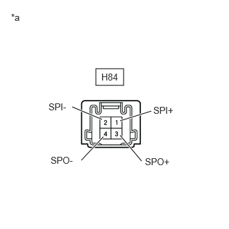
| *a | Component without harness connected
(Telematics Transceiver) |
Measure the resistance according to the value(s) in the table below.
- Standard Resistance:
Tester Connection Condition Specified Condition Click Location & Routing(H84)Location & Routingewd_type=routing;type=c;code=H84
Click Connector(H84)Instrument Panel>Instrument Panel Wire / Speaker Wire>Telematics Transceiverewd_type=component;type=c;code=H84;pinno=1,3,2,4
H84-1 (SPI+) - H84-3 (SPO+) Always Below 1 Ω H84-2 (SPI-) - H84-4 (SPO-) Always Below 1 Ω H84-1 (SPI+) - H84-2 (SPI-) Always 10 kΩ or higher H84-3 (SPO+) - H84-4 (SPO-) Always 10 kΩ or higher H84-1 (SPI+) or H84-3 (SPO+) - Body ground Always 10 kΩ or higher H84-2 (SPI-) or H84-4 (SPO-) - Body ground Always 10 kΩ or higher
- Result:
Proceed to OK NG
Post-procedure1
None
OK
NG
Pre-procedure1
Disconnect the H87 front No. 2 speaker assembly LH connector.
Disconnect the H84 telematics transceiver connector.
Procedure1
Measure the resistance according to the value(s) in the table below.
- Standard Resistance:
Tester Connection Condition Specified Condition Click Location & Routing(H87,H84)Location & Routingewd_type=routing;type=c,c;code=H87,H84
Click Connector(H87)Instrument Panel>Instrument Panel Wire / Speaker Wire>Front No. 2 Speaker Assembly LHewd_type=component;type=c;code=H87;pinno=3,1
Click Connector(H84)Instrument Panel>Instrument Panel Wire / Speaker Wire>Telematics Transceiverewd_type=component;type=c;code=H84;pinno=3,4
H87-3 (+) or H84-3 (SPO+) - Body ground Always 10 kΩ or higher H87-1 (-) or H84-4 (SPO-) - Body ground Always 10 kΩ or higher
- Result:
Proceed to OK NG
Post-procedure1
None
OK
NG
Pre-procedure1
Disconnect the K2 and L2 front No. 1 speaker assembly connectors.
Disconnect the H88 and H87 front No. 2 speaker assembly connectors.
Procedure1
Measure the resistance according to the value(s) in the table below.
- Standard Resistance:
Tester Connection Condition Specified Condition Click Location & Routing(H88,K2,H87,L2)Location & Routingewd_type=routing;type=c,c,c,c;code=H88,K2,H87,L2
Click Connector(H88)Instrument Panel>Instrument Panel Wire / Speaker Wire>Front No. 2 Speaker Assembly RHewd_type=component;type=c;code=H88;pinno=4,2
Click Connector(K2)Body>Front Door Wire RH / Television Camera Wire>Front No. 1 Speaker Assembly RHewd_type=component;type=c;code=K2;pinno=2,1
Click Connector(H87)Instrument Panel>Instrument Panel Wire / Speaker Wire>Front No. 2 Speaker Assembly LHewd_type=component;type=c;code=H87;pinno=4,2
Click Connector(L2)Body>Front Door Wire LH / Television Camera Wire>Front No. 1 Speaker Assembly LHewd_type=component;type=c;code=L2;pinno=2,1
H88-4 (TWR+) or K2-2 - Body ground Always 10 kΩ or higher H88-2 (TWR-) or K2-1 - Body ground Always 10 kΩ or higher H87-4 (TWL+) or L2-2 - Body ground Always 10 kΩ or higher H87-2 (TWL-) or L2-1 - Body ground Always 10 kΩ or higher
- Result:
Proceed to OK NG
Post-procedure1
None
OK
NG
Click hereAudio / Visual / Telematics>AUDIO / VIDEO>FRONT DOOR SPEAKER>INSPECTION
- Result:
Proceed to OK NG
OK
NG
Click hereAudio / Visual / Telematics>AUDIO / VIDEO>REAR DOOR SPEAKER>INSPECTION
- Result:
Proceed to OK NG
OK
NG
Replace the front No. 2 speaker assembly with a new or known good one.
Click hereAudio / Visual / Telematics>AUDIO / VIDEO>PILLAR SPEAKER>REMOVAL
- Result:
Proceed to NEXT
NEXT
Clear the DTCs.
- Body Electrical > Navigation System > Clear DTCs
- 50002 212
- Result:
Proceed to NEXT
NEXT
Clear the DTCs.
- Body Electrical > Navigation System > Trouble Codes
- 50001 212
- Result:
Result Proceed to DTCs are output A DTCs are not output B
A
B
Pre-procedure1
Disconnect the H83 radio and display receiver assembly connector.
Disconnect the H88 and H87 front No. 2 speaker assembly connectors.
Disconnect the M2 and N2 rear speaker assembly connectors.
Procedure1
Measure the resistance according to the value(s) in the table below.
- Standard Resistance:
Tester Connection Condition Specified Condition Click Location & Routing(H83,H88,H87,M2,N2)Location & Routingewd_type=routing;type=c,c,c,c,c;code=H83,H88,H87,M2,N2
Click Connector(H83)Instrument Panel>Instrument Panel Wire / Speaker Wire>Radio & Display Receiver Assemblyewd_type=component;type=c;code=H83;pinno=1,6,2,7,4,9,3,8
Click Connector(H88)Instrument Panel>Instrument Panel Wire / Speaker Wire>Front No. 2 Speaker Assembly RHewd_type=component;type=c;code=H88;pinno=3,1
Click Connector(H87)Instrument Panel>Instrument Panel Wire / Speaker Wire>Front No. 2 Speaker Assembly LHewd_type=component;type=c;code=H87;pinno=3,1
Click Connector(M2)Body>No. 1 Rear Door Wire>Rear Speaker Assembly RHewd_type=component;type=c;code=M2;pinno=2,1
Click Connector(N2)Body>No. 2 Rear Door Wire>Rear Speaker Assembly LHewd_type=component;type=c;code=N2;pinno=2,1
H83-1 (FR+) or H88-3 (+) - Body ground Always 10 kΩ or higher H83-6 (FR-) or H88-1 (-) - Body ground Always 10 kΩ or higher H83-2 (FL+) or H87-3 (+) - Body ground Always 10 kΩ or higher H83-7 (FL-) or H87-1 (-) - Body ground Always 10 kΩ or higher H83-4 (RR+) or M2-2 - Body ground Always 10 kΩ or higher H83-9 (RR-) or M2-1 - Body ground Always 10 kΩ or higher H83-3 (RL+) or N2-2 - Body ground Always 10 kΩ or higher H83-8 (RL-) or N2-1 - Body ground Always 10 kΩ or higher
- Result:
Proceed to OK NG
Post-procedure1
None
OK
NG
Pre-procedure1
Disconnect the K2 and L2 front No. 1 speaker assembly connectors.
Disconnect the H88 and H87 front No. 2 speaker assembly connectors.
Procedure1
Measure the resistance according to the value(s) in the table below.
- Standard Resistance:
Tester Connection Condition Specified Condition Click Location & Routing(H88,K2,H87,L2)Location & Routingewd_type=routing;type=c,c,c,c;code=H88,K2,H87,L2
Click Connector(H88)Instrument Panel>Instrument Panel Wire / Speaker Wire>Front No. 2 Speaker Assembly RHewd_type=component;type=c;code=H88;pinno=4,2
Click Connector(K2)Body>Front Door Wire RH / Television Camera Wire>Front No. 1 Speaker Assembly RHewd_type=component;type=c;code=K2;pinno=2,1
Click Connector(H87)Instrument Panel>Instrument Panel Wire / Speaker Wire>Front No. 2 Speaker Assembly LHewd_type=component;type=c;code=H87;pinno=4,2
Click Connector(L2)Body>Front Door Wire LH / Television Camera Wire>Front No. 1 Speaker Assembly LHewd_type=component;type=c;code=L2;pinno=2,1
H88-4 (TWR+) or K2-2 - Body ground Always 10 kΩ or higher H88-2 (TWR-) or K2-1 - Body ground Always 10 kΩ or higher H87-4 (TWL+) or L2-2 - Body ground Always 10 kΩ or higher H87-2 (TWL-) or L2-1 - Body ground Always 10 kΩ or higher
- Result:
Proceed to OK NG
Post-procedure1
None
OK
NG
Click hereAudio / Visual / Telematics>AUDIO / VIDEO>FRONT DOOR SPEAKER>INSPECTION
- Result:
Proceed to OK NG
OK
NG
Click hereAudio / Visual / Telematics>AUDIO / VIDEO>REAR DOOR SPEAKER>INSPECTION
- Result:
Proceed to OK NG
OK
NG
Replace the front No. 2 speaker assembly with a new or known good one.
- HINT:
-
Click hereAudio / Visual / Telematics>AUDIO / VIDEO>PILLAR SPEAKER>REMOVAL
- Result:
Proceed to NEXT
NEXT
Clear the DTCs.
- Body Electrical > Navigation System > Clear DTCs
- 50002 212
- Result:
Proceed to NEXT
NEXT
Check for DTCs.
- Body Electrical > Navigation System > Trouble Codes
- 50001 212
- Result:
Result Proceed to DTCs are output A DTCs are not output B
A
B
Pre-procedure1
Disconnect the H136 stereo component amplifier assembly connector.
Disconnect the K2 and L2 front No. 1 speaker assembly connectors.
Disconnect the H88 and H87 front No. 2 speaker assembly connectors.
Disconnect the H158 and H157 front No. 3 speaker assembly connectors.
Disconnect the M2 and N2 rear speaker assembly connectors.
Procedure1
Measure the resistance according to the value(s) in the table below.
- Standard Resistance:
Tester Connection Condition Specified Condition Click Location & Routing(H136,K2,L2,H88,H87,H157,H158,M2,N2)Location & Routingewd_type=routing;type=c,c,c,c,c,c,c,c,c;code=H136,K2,L2,H88,H87,H157,H158,M2,N2
Click Connector(H136)Instrument Panel>Instrument Panel Wire / Speaker Wire>Stereo Component Amplifier Assemblyewd_type=component;type=c;code=H136;pinno=10,25,8,23,14,29,12,27,11,26,9,24,15,30,13,28
Click Connector(K2)Body>Front Door Wire RH / Television Camera Wire>Front No. 1 Speaker Assembly RHewd_type=component;type=c;code=K2;pinno=2,1
Click Connector(L2)Body>Front Door Wire LH / Television Camera Wire>Front No. 1 Speaker Assembly LHewd_type=component;type=c;code=L2;pinno=2,1
Click Connector(H88)Instrument Panel>Instrument Panel Wire / Speaker Wire>Front No. 2 Speaker Assembly RHewd_type=component;type=c;code=H88;pinno=4,2
Click Connector(H87)Instrument Panel>Instrument Panel Wire / Speaker Wire>Front No. 2 Speaker Assembly LHewd_type=component;type=c;code=H87;pinno=4,2
Click Connector(H157)Instrument Panel>Instrument Panel Wire / Speaker Wire>No. 3 Front Speaker Assembly RHewd_type=component;type=c;code=H157;pinno=2,1
Click Connector(H158)Instrument Panel>Instrument Panel Wire / Speaker Wire>No. 3 Front Speaker Assembly LHewd_type=component;type=c;code=H158;pinno=2,1
Click Connector(M2)Body>No. 1 Rear Door Wire>Rear Speaker Assembly RHewd_type=component;type=c;code=M2;pinno=2,1
Click Connector(N2)Body>No. 2 Rear Door Wire>Rear Speaker Assembly LHewd_type=component;type=c;code=N2;pinno=2,1
H136-10 (WFR+) or K2-2 - Body ground Always 10 kΩ or higher H136-25 (WFR-) or K2-1 - Body ground Always 10 kΩ or higher H136-8 (WFL+) or L2-2 - Body ground Always 10 kΩ or higher H136-23 (WFL-) or L2-1 - Body ground Always 10 kΩ or higher H136-14 (TWR+) or H88-4 - Body ground Always 10 kΩ or higher H136-29 (TWR-) or H88-2 - Body ground Always 10 kΩ or higher H136-12 (TWL+) or H87-4 - Body ground Always 10 kΩ or higher H136-27 (TWL-) or H87-2 - Body ground Always 10 kΩ or higher H136-11 (FR+) or H157-2 - Body ground Always 10 kΩ or higher H136-26 (FR-) or H157-1 - Body ground Always 10 kΩ or higher H136-9 (FL+) or H158-2 - Body ground Always 10 kΩ or higher H136-24 (FL-) or H158-1 - Body ground Always 10 kΩ or higher H136-15 (RR+) or M2-2 - Body ground Always 10 kΩ or higher H136-30 (RR-) or M2-1 - Body ground Always 10 kΩ or higher H136-13 (RL+) or N2-2 - Body ground Always 10 kΩ or higher H136-28 (RL-) or N2-1 - Body ground Always 10 kΩ or higher
- Result:
Proceed to OK NG
Post-procedure1
None
OK
NG
Click hereAudio / Visual / Telematics>AUDIO / VIDEO>FRONT DOOR SPEAKER>INSPECTION
- Result:
Proceed to OK NG
OK
NG
Click hereAudio / Visual / Telematics>AUDIO / VIDEO>INSTRUMENT PANEL SPEAKER>INSPECTION
- Result:
Proceed to OK NG
OK
NG
Click hereAudio / Visual / Telematics>AUDIO / VIDEO>REAR DOOR SPEAKER>INSPECTION
- Result:
Proceed to OK NG
OK
NG
Replace the front No. 2 speaker assembly with a new or known good one.
Click hereAudio / Visual / Telematics>AUDIO / VIDEO>PILLAR SPEAKER>REMOVAL
- Result:
Proceed to NEXT
NEXT
Clear the DTCs.
- Body Electrical > Navigation System > Clear DTCs
- 50002 212
- Result:
Proceed to NEXT
NEXT
Check for DTCs.
- Body Electrical > Navigation System > Trouble Codes
- 50001 212
- Result:
Result Proceed to DTCs are output A DTCs are not output B
A
B