PARK ASSIST / MONITORING TOYOTA PARKING ASSIST-SENSOR SYSTEM(w/ Parking Support Brake System) C1AF287 Ultrasonic Sensor (Rear Right Side) Missing Message
DESCRIPTION
This DTC is output when an open circuit or short occurs in the communication line between a rear side ultrasonic sensor (RRS sensor) and the rear side ultrasonic sensor (RLS sensor) or when a malfunction occurs in a rear side ultrasonic sensor (RRS sensor) on the rear.
| DTC No. | Detection Item | DTC Detection Condition | Trouble Area | DTC Output from | Priority |
|---|---|---|---|---|---|
| C1AF287 | Ultrasonic Sensor (Rear Right Side) Missing Message | Rear side ultrasonic sensor (RRS sensor) lost communication | ·
Rear side ultrasonic sensor (RRS sensor) ·
Harness or connector ·
Clearance warning ECU assembly |
Clearance Warning | B |
WIRING DIAGRAM
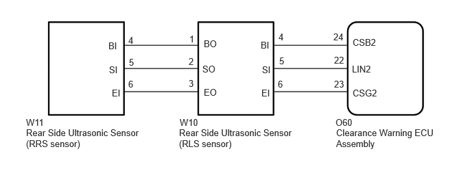
CAUTION / NOTICE / HINT
- NOTICE:
- ·
Perform registration after replacing or removing and installing the ultrasonic sensor or clearance warning ECU assembly.
·If a DTC is detected again after the repair, turn the ignition switch to ON and turn the TOYOTA parking assist-sensor system on, and then clear the DTC.
·If C1AF196 is output at the same time, check C1AF196 first.
PROCEDURE
Check the vehicle condition and work details.
- Result:
Result Proceed to The clearance warning ECU assembly or ultrasonic sensor has not been replaced A The clearance warning ECU assembly or ultrasonic sensor has been replaced B
A
B
Click hereAudio / Visual / Telematics>PARK ASSIST / MONITORING>PARKING SUPPORT BRAKE SYSTEM>CALIBRATION
Check that the connector is properly connected to the rear side ultrasonic sensor.
- Result:
Proceed to NEXT
NEXT
Clear the DTCs.
- Body Electrical > Clearance Warning > Clear DTCs
- 50002 438
- Result:
Proceed to NEXT
NEXT
Check for DTCs.
- Body Electrical > Clearance Warning > Trouble Codes
- 50001 438
- Result:
Result Proceed to DTCs are not output A C1AF287 is output B None of the above conditions are met C
A
B
C
Check that the connector is properly connected to the clearance warning ECU assembly.
- Result:
Proceed to NEXT
NEXT
Clear the DTCs.
- Body Electrical > Clearance Warning > Clear DTCs
- 50002 438
- Result:
Proceed to NEXT
NEXT
Check for DTCs.
- Body Electrical > Clearance Warning > Trouble Codes
- 50001 438
- Result:
Result Proceed to DTCs are not output A C1AF187 and C1AF287 are output B C1AF287 is output C None of the above conditions are met D
A
Click hereGeneral>INTRODUCTION>HOW TO TROUBLESHOOT ECU CONTROLLED SYSTEMS>HOW TO PROCEED WITH TROUBLESHOOTING
B
C
D
Pre-procedure1
Disconnect the W10 rear side ultrasonic sensor (RLS sensor) connector.
Disconnect the W11 rear side ultrasonic sensor (RRS sensor) connector.
Procedure1
Measure the resistance according to the value(s) in the table below.
- Standard Resistance:
Tester Connection Condition Specified Condition Click Location & Routing(W10,W11)Location & Routingewd_type=routing;type=c,c;code=W10,W11
Click Connector(W10)Body>No. 2 Luggage Room Wire>Rear Ultrasonic Sensor Side LHewd_type=component;type=c;code=W10;pinno=1,2,3
Click Connector(W11)Body>No. 2 Luggage Room Wire>Rear Ultrasonic Sensor Side RHewd_type=component;type=c;code=W11;pinno=4,5,6
W10-1 (BO) - W11-4 (BI) Always Below 1 Ω W10-2 (SO) - W11-5 (SI) Always Below 1 Ω W10-3 (EO) - W11-6 (EI) Always Below 1 Ω W10-1 (BO) or W11-4 (BI) - Body ground Always 10 kΩ or higher W10-2 (SO) or W11-5 (SI) - Body ground Always 10 kΩ or higher W10-3 (EO) or W11-6 (EI) - Body ground Always 10 kΩ or higher
- Result:
Proceed to OK NG
Post-procedure1
None
OK
NG
Replace the rear side ultrasonic sensor (RRS sensor) with a known good one.
- HINT:
- ··
All of the sensors are interchangeable. To confirm whether a sensor is functioning normally, switch it with a known good sensor from the other end of the vehicle.
- Result:
Proceed to NEXT
NEXT
Clear the DTCs.
- Body Electrical > Clearance Warning > Clear DTCs
- 50002 438
- Result:
Proceed to NEXT
NEXT
Check for DTCs.
- Body Electrical > Clearance Warning > Trouble Codes
- 50001 438
- Result:
Result Proceed to DTCs are not output A C1AF287 is output B None of the above conditions are met C
A
B
C