ADVANCED DRIVER ASSISTANCE SYSTEM ADAPTIVE HIGH BEAM SYSTEM U018287 Lost Communication with Lighting Control Module Front Missing Message
DESCRIPTION
The forward recognition camera communicates with the headlight ECU sub-assembly LH via CAN communication. If communication between the forward recognition camera and headlight ECU sub-assembly LH stops, the forward recognition camera will store this DTC.
| DTC No. | Detection Item | DTC Detection Condition | Trouble Area | DTC Output from | Priority |
|---|---|---|---|---|---|
| U018287 | Lost Communication with Lighting Control Module Front Missing Message | Detection condition:
The ignition switch is ON. Malfunction status:
A communication malfunction with the headlight ECU sub-assembly LH is detected Malfunction duration:
5 seconds or more |
·
Pre-collision system ·
Headlight ECU sub-assembly LH ·
Harness or connector |
Front Recognition Camera (Front Lighting Control) | B |
| Pattern | DTC output part name
(Display on GTS) |
Suspected Area (Malfunction Status) | ||||||
|---|---|---|---|---|---|---|---|---|
| Forward Recognition Camera | Headlight ECU Sub-assembly LH | Millimeter Wave Radar Sensor Assembly | ||||||
| Forward Recognition Camera (Front Lighting Control) | Lane Control | Pre-Collision System | Radar Cruise2 | Headlight Control | Front Radar Sensor | |||
| U018287 | U023587 | U023587 | U023587 | U023587 | U023A87 | U010487 | ||
|
○: DTC is output -: DTC is not output |
||||||||
| Pattern 1 | ○ | ○ | ○ | ○ | ○ | ○ | ○ | Harness or connector (Open or short) |
| Headlight ECU sub-assembly LH (Internal malfunction) | ||||||||
| Millimeter wave radar sensor assembly (Internal malfunction) | ||||||||
| Forward recognition camera (Internal malfunction) | ||||||||
| Pattern 2 | ○ | ○ | ○ | ○ | ○ | - | - | Forward recognition camera (Internal malfunction) |
| Pattern 3 | ○ | - | - | - | - | ○ | - | Harness or connector (Open) |
| Headlight ECU sub-assembly LH (Internal malfunction) | ||||||||
| Pattern 4 | ○ | - | - | - | - | - | - | Headlight ECU sub-assembly LH (Internal malfunction) |
- HINT:
-
If the DTCs are output simultaneously, the inspection area can be narrowed down.
WIRING DIAGRAM
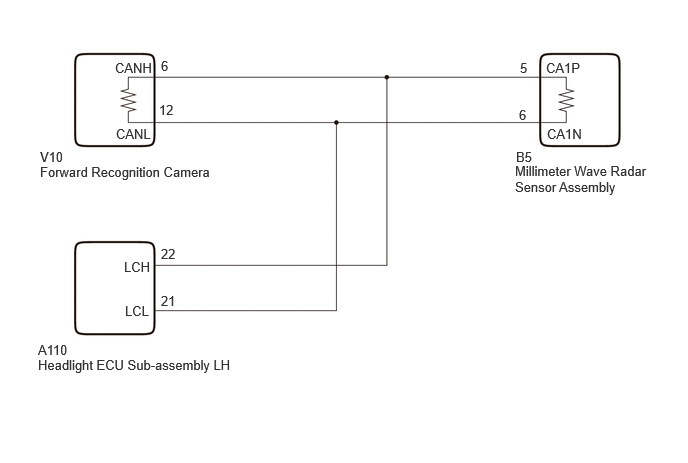
CAUTION / NOTICE / HINT
- NOTICE:
- ·
If the headlight ECU sub-assembly LH has been replaced, it is necessary to synchronize the vehicle information and initialize the headlight ECU sub-assembly LH.
Click hereVehicle Exterior>LIGHTING (EXT)>LIGHTING SYSTEM (w/ Adaptive High Beam System)>INITIALIZATION
·When replacing the headlight ECU sub-assembly LH, always replace it with a new one. If a headlight ECU sub-assembly LH which was installed to another vehicle is used, the information stored in it will not match the information from the vehicle and a DTC may be stored.
PROCEDURE
Check for DTCs.
- Body Electrical > Pre-Collision System > Trouble Codes
- 50001 432
- Result:
Result Proceed to U023587 is not output A U023587 is output B
A
B
Check for DTCs.
- Body Electrical > Headlight Control > Trouble Codes
- 50001 462
- Result:
Result Proceed to U023A87 is not output A U023A87 is output B
A
B
Pre-procedure1
Disconnect the A110 headlight ECU sub-assembly LH connector.
Disconnect the cable from the negative (-) auxiliary battery terminal.
Procedure1
Measure the resistance according to the value(s) in the table below.
- Standard Resistance:
Tester Connection Condition Specified Condition Click Location & Routing(A110)Location & Routingewd_type=routing;type=c;code=A110
Click Connector(A110)Engine Compartment>Engine Room Main Wire>Headlight ECU Sub-Assembly LHewd_type=component;type=c;code=A110;pinno=22,21
A110-22 (LCH) - A110-21 (LCL) Cable disconnected from negative (-) auxiliary battery terminal 54 to 69 Ω
- Result:
Proceed to OK NG
Post-procedure1
None
OK
NG