BRAKE SYSTEM (OTHER) BRAKE MASTER CYLINDER(for LHD) INSTALLATION
PROCEDURE

 47201
1.INSTALL BRAKE MASTER CYLINDER SUB-ASSEMBLY (w/o VSC)
Install a new O-ring onto the brake master cylinder sub-assembly.
Install the brake master cylinder sub-assembly with the 2 nuts.
- Torque:
- 13 N*m (128 kgf*cm, 9 ft.*lbf)
Using a union nut wrench 10 mm, install the 2 brake tubes onto the brake master cylinder sub-assembly.
- Torque:
- 15 N*m (155 kgf*cm, 11 ft.*lbf)
- NOTICE:
-
Use the formula to calculate special torque values for situations where a union nut wrench is combined with a torque wrench (See page General>INTRODUCTION>REPAIR INSTRUCTION>PRECAUTION).
Connect the brake fluid level warning switch connector.
47201
2.INSTALL BRAKE MASTER CYLINDER SUB-ASSEMBLY (w/ VSC)
Install a new O-ring onto the brake master cylinder sub-assembly.
Install the brake master cylinder sub-assembly with the 2 nuts.
- Torque:
- 13 N*m (128 kgf*cm, 9 ft.*lbf)
Using a union nut wrench 12 mm, install the 2 brake tubes onto the brake master cylinder sub-assembly.
- Torque:
- 20 N*m (199 kgf*cm, 14 ft.*lbf)
- NOTICE:
-
Use the formula to calculate special torque values for situations where a union nut wrench is combined with a torque wrench (See page General>INTRODUCTION>REPAIR INSTRUCTION>PRECAUTION).
Connect the brake fluid level warning switch connector.
31434
3.CONNECT CLUTCH RESERVOIR TUBE (for Manual Transaxle)
Connect the clutch reservoir tube with the clip.
74411
4.INSTALL BATTERY CARRIER
Install the battery carrier with the 5 bolts.
- Torque:
- 17 N*m (173 kgf*cm, 13 ft.*lbf)
Engage the 6 wire harness clamps and install the wire harness.
74431
5.INSTALL BATTERY TRAY
28800
6.INSTALL BATTERY
7.BLEED BRAKE LINE
8.BLEED CLUTCH LINE (for Manual Transaxle)
(See page Drivetrain>CLUTCH>CLUTCH SYSTEM>BLEEDING)
9.INSTALL CENTER COWL TOP VENTILATOR LOUVER
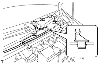
Engage the 2 claws and 6 guides and install the cowl top ventilator louver center.
Engage the 2 claws and install the washer hose joint.
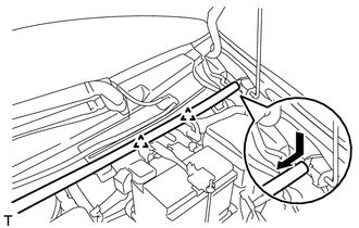
Engage the 2 clips and slide the hood to cowl top seal as shown in the illustration.