2NZ-FE ENGINE MECHANICAL ENGINE ASSEMBLY INSTALLATION
PROCEDURE

 12372A
1.INSTALL ENGINE MOUNTING INSULATOR LH
- HINT:
-
Only perform this procedure when replacement of the engine mounting insulator LH is necessary.
Install the engine mounting insulator LH with the 5 bolts.
- Torque:
- 52 N*m (530 kgf*cm, 38 ft.*lbf)
12305
2.INSTALL ENGINE MOUNTING INSULATOR RH
- HINT:
-
Only perform this procedure when replacement of the engine mounting insulator RH is necessary.
Install the engine mounting insulator RH with the 3 bolts.
- Torque:
- 52 N*m (530 kgf*cm, 38 ft.*lbf)
12321B
3.INSTALL DRIVE SHAFT HEAT INSULATOR SUB-ASSEMBLY
Install the drive shaft heat insulator sub-assembly with the bolt and nut.
- Torque:
- 18 N*m (183 kgf*cm, 13 ft.*lbf)
87245A
4.CONNECT INLET HEATER WATER HOSE A
Connect heater water inlet hose A to the cylinder head.
17167
5.INSTALL NO. 1 EXHAUST MANIFOLD HEAT INSULATOR
Install the exhaust manifold insulator with the 4 bolts.
- Torque:
- 8.0 N*m (82 kgf*cm, 71 in.*lbf)
6.FIX ENGINE ASSEMBLY
Using an engine sling device and a chain block, hold the engine assembly.
Use a belt with a tightening mechanism or a rope to secure the engine assembly with transaxle to the engine lifter.
- NOTICE:
- ·
Set plate lift attachments so that the engine assembly with transaxle is level.
·Do not perform any procedure while the engine assembly is suspended because doing so may cause the engine assembly to drop, resulting in injury. However, the engine assembly needs to be suspended when it is installed to or removed from an engine stand.
·To prevent deformation of the oil pan, never set any attachments against the oil pan of the engine assembly.
32101B
7.INSTALL DRIVE PLATE AND RING GEAR SUB-ASSEMBLY (for Automatic Transaxle)
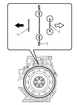
Using SST, hold the crankshaft.
- SST
- 09960-10010 (09962-01000, 09963-01000)
Clean the 6 bolts and their holes.
Install the front drive plate spacer.
| *1 | Front Drive Plate Spacer |
| *2 | Drive Plate and Ring Gear |
| *3 | Rear Drive Plate Spacer |

|
Engine Side |

|
Transaxle Side |
Install the drive plate and rear drive plate spacer onto the crankshaft.
- HINT:
- ·
The front drive plate spacer is reversible.
·As the drive plate and ring gear and the rear drive plate spacer are not reversible, make sure to install them in the direction as shown in the illustration.
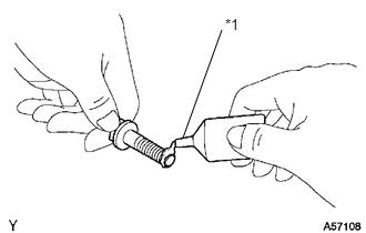
Apply adhesive to the end 2 or 3 threads of the 6 bolts.
- Adhesive:
Toyota Genuine Adhesive 1324, Three Bond 1324 or equivalent
Install the drive plate spacer RR, drive plate and ring gear sub-assembly and drive plate spacer FR.
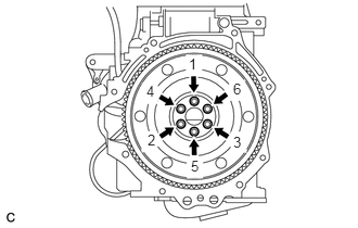
Install and uniformly tighten the 6 bolts in several steps, in the sequence shown in the illustration.
- Torque:
- 88 N*m (897 kgf*cm, 65 ft.*lbf)
- NOTICE:
-
Do not start the engine for at least 1 hour after performing the installation.
13405
8.INSTALL FLYWHEEL SUB-ASSEMBLY (for Manual Transaxle)
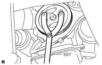
Hold the crankshaft with SST.
- SST
- 09960-10010 (09962-01000, 09963-01000)
Clean the 6 bolts and their holes.
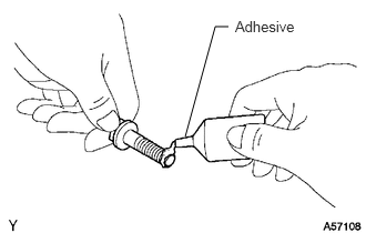
Apply adhesive to the end 2 or 3 threads of new bolts.
- Adhesive:
Toyota Genuine Adhesive 1324, Three Bond 1324 or equivalent
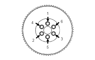
Install the flywheel with the 6 bolts in the order shown in the illustration.
- Torque:
- 49 N*m (500 kgf*cm, 38 ft.*lbf)
Mark a paint mark on each bolt head on the engine upper side.
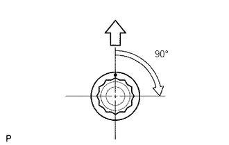
Tighten the bolts 90° in the sequence shown in the illustration.
- NOTICE:
-
Do not start the engine for at least 1 hour after performing the installation.
31250
9.INSTALL CLUTCH DISC ASSEMBLY (for Manual Transaxle)
31210
10.INSTALL CLUTCH COVER ASSEMBLY (for Manual Transaxle)
31210
11.INSPECT AND ADJUST CLUTCH COVER ASSEMBLY (for Manual Transaxle)
30500
12.INSTALL AUTOMATIC TRANSAXLE ASSEMBLY (for Automatic Transaxle)
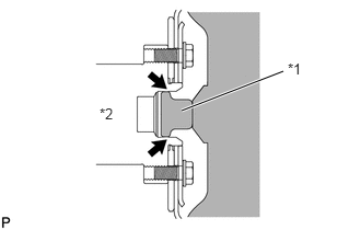
Apply clutch spline grease to the surface of the crankshaft that contacts the torque converter centerpiece.
| *1 | Torque Converter Centerpiece |
| *2 | Crankshaft |
- Clutch spline grease:
Toyota Genuine Clutch Spline Grease or equivalent
- Maximum spread:
About 1 g (0.0353 oz.)
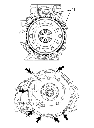
While keeping the engine and automatic transaxle assembly horizontal, align the knock pins with the holes in the automatic transaxle assembly and install the 7 bolts shown in the illustration.
| *1 | Knock Pin |
- Torque:
- 30 N*m (301 kgf*cm, 22 ft.*lbf)
- NOTICE:
- ·
Confirm that the 2 knock pins are installed to the transaxle contact surface of the engine cylinder block before installing the transaxle.
·Do not forcibly pry on the Check that the torque converter rotates.
·Check that the torque converter rotates.
Install the wire harness bracket with the bolt.
- Torque:
- 13 N*m (130 kgf*cm, 9 ft.*lbf)
- NOTICE:
- ·
To avoid damage to the input shaft, do not forcefully shake the transaxle.
·Insert knock pins into the knock pin holes securely so that the end face of the transaxle fits close against the engine before tightening the bolts.
30300
13.INSTALL MANUAL TRANSAXLE ASSEMBLY (for Manual Transaxle)
Install the manual transaxle assembly with the 7 bolts.
- Torque:
- 33 N*m (336 kgf*cm, 24 ft.*lbf)
33524F
14.INSTALL CONTROL CABLE BRACKET (for Manual Transaxle)
Install the floor shift control lever housing support bracket with the 2 bolts.
- Torque:
- 25 N*m (255 kgf*cm, 18 ft.*lbf)
28100
15.INSTALL STARTER ASSEMBLY
11363A
16.INSTALL FLYWHEEL HOUSING SIDE COVER
17141
17.INSTALL EXHAUST MANIFOLD
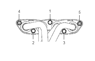
Tighten the exhaust manifold nuts and bolts, in the order shown in the illustration, through a new gasket.
- Torque:
- 27 N*m (275 kgf*cm, 20 ft.*lbf)
25591
18.INSTALL MANIFOLD SUPPORT BRACKET
Install the manifold support bracket with the 3 bolts.
- Torque:
- 44 N*m (449 kgf*cm, 33 ft.*lbf)
17167
19.INSTALL NO. 1 EXHAUST MANIFOLD HEAT INSULATOR
Install the No. 1 exhaust manifold heat insulator with the 3 bolts.
- Torque:
- 8.0 N*m (82 kgf*cm, 71 in.*lbf)
17111
20.INSTALL INTAKE MANIFOLD
Install a new gasket onto the intake manifold.
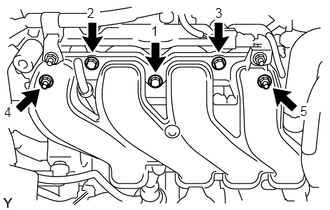
Provisionally tighten the intake manifold nuts and bolts in the order shown in the illustration, and then tighten them to the specified torque.
- Torque:
- 30 N*m (306 kgf*cm, 22 ft.*lbf)
Connect the water by-pass hose to No. 1 water bypass pipe.
Connect the water by-pass hose to the cylinder head.
Connect the union to connector tube hose to the booster vacuum tube with the hose clamp.
16502
21.INSTALL WATER FILLER SUB-ASSEMBLY
Install the water filler sub-assembly with the 2 nuts.
- Torque:
- 7.5 N*m (76 kgf*cm, 66 in.*lbf)
Connect the No. 1 radiator hose to the cylinder head with the hose clamp.
19500D
22.INSTALL NO. 1 IGNITION COIL
51201
23.INSTALL FRONT SUSPENSION CROSSMEMBER SUB-ASSEMBLY
Install the engine moving control rod with the through bolt.
- Torque:
- 120 N*m (1244 kgf*cm, 89 ft.*lbf)
24.INSTALL ENGINE WIRE
Connect all the wire harnesses and connectors.
Install the 2 ground bolts.
- Torque:
- 8.4 N*m (85 kgf*cm, 74 in.*lbf)
12281A
25.REMOVE NO. 1 ENGINE HANGER
Remove the 2 bolts and the No. 1 engine hanger.
Install the oxygen sensor wiring bracket with the 2 bolts.
- Torque:
- 61 N*m (622 kgf*cm, 45 ft.*lbf)
26.INSTALL ENGINE ASSEMBLY WITH TRANSAXLE
- SST
- 09670-00010
Place wooden blocks or plate lift attachments on an engine lifter, and then set the engine assembly with transaxle.
- NOTICE:
- ·
Place the wooden blocks or plate lift attachments so that the engine assembly with transaxle is level.
·As the engine assembly with transaxle is very heavy, be sure to support it securely.
Operate the engine lifter and lift the engine assembly with transaxle and the front suspension crossmember to the position where the engine mounting insulators RH and LH can be installed.
Install the engine mounting insulator LH with the through bolt and nut.
- Torque:
- 52 N*m (530 kgf*cm, 38 ft.*lbf)
- HINT:
-
Tighten by holding the nut and turning the bolt.
Install the engine mounting insulator RH with the bolt and 2 nuts.
- Torque:
- 52 N*m (530 kgf*cm, 38 ft.*lbf)
By inserting SST into the datum holes in the front suspension crossmember RH and LH alternately, tighten bolts A, B and C on both sides to the specified torque, in several steps.
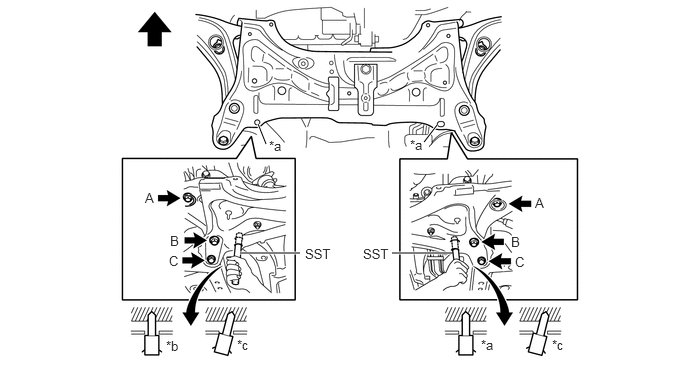
| *a | Datum Hole | *b | OK |
| *c | NG | - | - |
|
|
Front of the Vehicle | - | - |
- Torque:
- Bolt A : 87 N*m (887 kgf*cm, 64 ft.*lbf)
- Bolt B : 151 N*m (1540 kgf*cm, 111 ft.*lbf)
- Bolt C : 98 N*m (999 kgf*cm, 72 ft.*lbf)
- NOTICE:
- ·
Insert SST into the datum hole vertically.
·If impossible to insert SST vertically, loosen all bolts and then insert SST again.
45025D
27.INSTALL NO. 1 STEERING COLUMN HOLE COVER SUB-ASSEMBLY
45209
28.INSTALL STEERING SLIDING YOKE SUB-ASSEMBLY
45259A
29.INSTALL COLUMN HOLE COVER SILENCER SHEET
32101G
30.INSTALL TORQUE CONVERTER SETTING BOLT (for Automatic Transaxle)
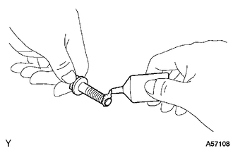
Remove any adhesive remaining in the 6 bolt holes of the torque converter clutch and 6 bolts.
Apply adhesive to 2 or 3 threads on the end of the 6 bolts.
- Adhesive:
Toyota Genuine Adhesive 1324, Three Bond 1324 or equivalent
Hold the crankshaft pulley with SST.
- SST
- 09960-10010 (09962-01000, 09963-01000)
Tighten the 6 torque converter set bolts.
- Torque:
- 28 N*m (286 kgf*cm, 21 ft.*lbf)
11361J
31.INSTALL FLYWHEEL HOUSING UNDER COVER
43420
32.INSTALL FRONT DRIVE SHAFT ASSEMBLY LH
17451
33.INSTALL EXHAUST PIPE GASKET
17451A
34.INSTALL NO. 2 EXHAUST PIPE GASKET
17410
35.INSTALL FRONT EXHAUST PIPE ASSEMBLY
57533B
36.INSTALL FRONT FLOOR CENTER BRACE (w/ Side Mudguard)
33820B
37.INSTALL TRANSMISSION CONTROL CABLE ASSEMBLY (for Automatic Transaxle)
33820B
38.ADJUST TRANSMISSION CONTROL CABLE ASSEMBLY (for Automatic Transaxle)
33820B
39.INSTALL TRANSMISSION CONTROL CABLE ASSEMBLY (for Manual Transaxle)
58910C
40.INSTALL REAR CONSOLE BOX ASSEMBLY
41.CONNECT ENGINE WIRE
for Automatic Transaxle:
Engage the clamp and connect the wire harness to the automatic transaxle.
Install the wire harness to the automatic transaxle with the bolt.
- Torque:
- 26 N*m (260 kgf*cm, 19 ft.*lbf)
Connect the 2 connectors to the battery positive terminal.
Engage the 2 claws and connect the wire harness to the engine room relay block.
Connect the connector to the engine room relay block.
Engage the clamp and connect the wire harness to the body.
Pull down the lever to engage the lock and connect the connector to the ECM.
Engage the clamp and connect the wire harness to the wire harness bracket.
Connect all the wire harness and connectors.
88310
42.INSTALL COMPRESSOR WITH PULLEY ASSEMBLY (w/ Air Conditioning System)
31470
43.INSTALL CLUTCH RELEASE CYLINDER ASSEMBLY (for Manual Transaxle)
16361A
44.INSTALL FAN AND GENERATOR V BELT
16361A
45.ADJUST FAN AND GENERATOR V BELT
87245A
46.CONNECT INLET HEATER WATER HOSE A
Connect inlet heater water hose A to the heater unit with the hose clamp.
87246A
47.CONNECT OUTLET HEATER WATER HOSE A
Connect outlet heater water hose A to the heater unit with the hose clamp.
44773F
48.CONNECT UNION TO CHECK VALVE HOSE
Connect the union to check valve hose to the booster vacuum tube with the hose clamp.
23901
49.CONNECT FUEL TUBE SUB-ASSEMBLY
Connect the fuel tube connector and fuel pipe.
- CAUTION:
-
Align the fuel tube connector with the pipe, then push the fuel tube connector in until the retainer makes a click sound. If the connection is tight, apply a small amount of engine oil to the tip of the pipe. After connecting, pull the pipe and connector to make sure that they are securely connected.
23842A
50.INSTALL EFI FUEL PIPE CLAMP
Install the EFI fuel pipe clamp.
51.CONNECT INLET OIL COOLER HOSE (for Automatic Transaxle)
Connect the oil cooler inlet hose with the clip.
52.CONNECT OUTLET OIL COOLER HOSE (for Automatic Transaxle)
Connect the oil cooler outlet hose with the clip.
16572D
53.CONNECT NO. 2 RADIATOR HOSE
Connect the No. 2 radiator hose to the water inlet with the hose clamp.
16573B
54.CONNECT NO. 3 RADIATOR HOSE
Connect No. 3 radiator hose to the water filler with the hose clamp.
55.CONNECT RADIATOR RESERVOIR TANK HOSE
Connect the radiator reservoir tank hose to the water filler.
23820
56.INSTALL FUEL VAPOR FEED HOSE ASSEMBLY
Install fuel vapor feed hose assembly with the 2 hose clamps.
74411
57.INSTALL BATTERY CARRIER (for LHD)
Install the battery carrier with the 5 bolts.
- Torque:
- 17 N*m (173 kgf*cm, 13 ft.*lbf)
Engage the 6 wire harness clamps and install the wire harness.
74411
58.INSTALL BATTERY CARRIER (for RHD)
Install the battery carrier with the 5 bolts.
- Torque:
- 17 N*m (173 kgf*cm, 13 ft.*lbf)
Engage the 7 wire harness clamps and install the wire harness.
17771A
59.INSTALL AIR CLEANER BRACKET
Install the air cleaner bracket with the 2 bolts.
- Torque:
- 20 N*m (199 kgf*cm, 14 ft.*lbf)
Connect the wire harness clamp to the air cleaner bracket.
17700
60.INSTALL AIR CLEANER ASSEMBLY
Install the air cleaner case onto the air cleaner bracket with the 2 bolts.
- Torque:
- 7.8 N*m (80 kgf*cm, 69 in.*lbf)
Engage the clamp and connect the wire harness to the air cleaner case.
Install the air cleaner element onto the air cleaner case.
Install the air cleaner cap sub-assembly with No. 1 air cleaner hose onto the throttle body assembly.
Engage the 2 clamps and connect the air cleaner cap sub-assembly to the air cleaner case subassembly.
Tighten the hose clamp.
- Torque:
- 3.0 N*m (31 kgf*cm, 27 in.*lbf)
Connect the vacuum switching valve assembly connector.
Connect the mass air flow meter connector.
Engage the 2 clamps and connect the wire harness to the air cleaner cap sub-assembly and vacuum switching valve assembly.
Connect the No. 2 fuel vapor feed hose to the intake manifold.
Connect the fuel vapor feed hose assembly to the No. 1 air cleaner hose and vacuum switching valve assembly with the 2 hose clamps.
Engage the clamp and connect the fuel vapor feed hose assembly to the No. 1 air cleaner hose.
74431
61.INSTALL BATTERY TRAY
28800
62.INSTALL BATTERY
Install the battery onto the vehicle with the battery clamp.
- Torque:
- 3.5 N*m (36 kgf*cm, 31 in.*lbf)
Connect the cable to the battery terminal.
- Torque:
- 5.4 N*m (55 kgf*cm, 48 in.*lbf)
55711
63.REMOVE OUTER COWL TOP PANEL (for LHD)
55711
64.INSTALL OUTER COWL TOP PANEL (for RHD)
55722C
65.INSTALL INNER COWL TOP TO COWL BRACE (for LHD)
55722C
66.INSTALL INNER COWL TOP TO COWL BRACE (for RHD)
55815E
67.INSTALL FRONT NO. 1 VENTILATOR SEAL (for LHD)
55815E
68.INSTALL FRONT NO. 1 VENTILATOR SEAL (for RHD)
55735D
69.INSTALL FRONT AIR SHUTTER SEAL RH (for LHD)
55735D
70.INSTALL FRONT AIR SHUTTER SEAL RH (for RHD)
71.INSTALL WINDSHIELD WIPER MOTOR AND LINK ASSEMBLY
72.INSTALL FRONT WHEELS
- Torque:
- 103 N*m (1050 kgf*cm, 76 ft.*lbf)
16361A
73.INSPECT FAN AND GENERATOR V BELT
74.ADD ENGINE COOLANT
75.INSPECT ENGINE OIL LEVEL
76.ADD AUTOMATIC TRANSAXLE FLUID (for Automatic Transaxle)
77.INSPECT AUTOMATIC TRANSAXLE FLUID (for Automatic Transaxle)
78.ADD MANUAL TRANSAXLE OIL (for Manual Transaxle)
79.INSPECT MANUAL TRANSAXLE OIL (for Manual Transaxle)
80.INSPECT FOR COOLANT LEAK
81.INSPECT FOR OIL LEAK
82.INSPECT FOR AUTOMATIC TRANSAXLE FLUID LEAK
83.INSPECT FOR MANUAL TRANSAXLE OIL LEAK
84.INSPECT FOR FUEL LEAK
85.INSPECT FOR EXHAUST GAS LEAK
86.INSPECT IGNITION TIMING
87.INSPECT ENGINE IDLING SPEED
89.INSPECT AND ADJUST FRONT WHEEL ALIGNMENT
51441C
90.INSTALL ENGINE UNDER COVER RH (for Plastic Type)
- Torque:
- 5.0 N*m (51 kgf*cm, 44 in.*lbf)
51442C
91.INSTALL ENGINE UNDER COVER LH (for Plastic Type)
- Torque:
- 5.0 N*m (51 kgf*cm, 44 in.*lbf)
92.INSTALL NO. 1 ENGINE UNDER COVER SUB-ASSEMBLY (for Metal Type)
- Torque:
- 18 N*m (184 kgf*cm, 13 ft.*lbf)
11212
93.INSTALL NO. 2 CYLINDER HEAD COVER
94.INSPECT ABS SENSOR SIGNAL (w/o VSC)
95.INSPECT VSC SPEED SENSOR SIGNAL