Home › Audio / Visual / Telematics › AUDIO / VIDEO › AUDIO AND VISUAL SYSTEM
RM19S0E _56 Audio / Visual / Telematics _051483 AUDIO / VIDEO _0248261 AUDIO AND VISUAL SYSTEM J

AUDIO / VIDEO  AUDIO AND VISUAL SYSTEM  Steering Pad Switch Circuit  


DESCRIPTION

This circuit sends an operation signal from the steering pad switch assembly to the radio receiver assembly.

If there is an open in the circuit, the audio system cannot be operated using the steering pad switch assembly.

If there is a short in the circuit, the same condition as when a switch is continuously depressed occurs. Therefore, the radio receiver assembly cannot be operated using the steering pad switch assembly, and also the radio receiver assembly itself cannot function.

WIRING DIAGRAM
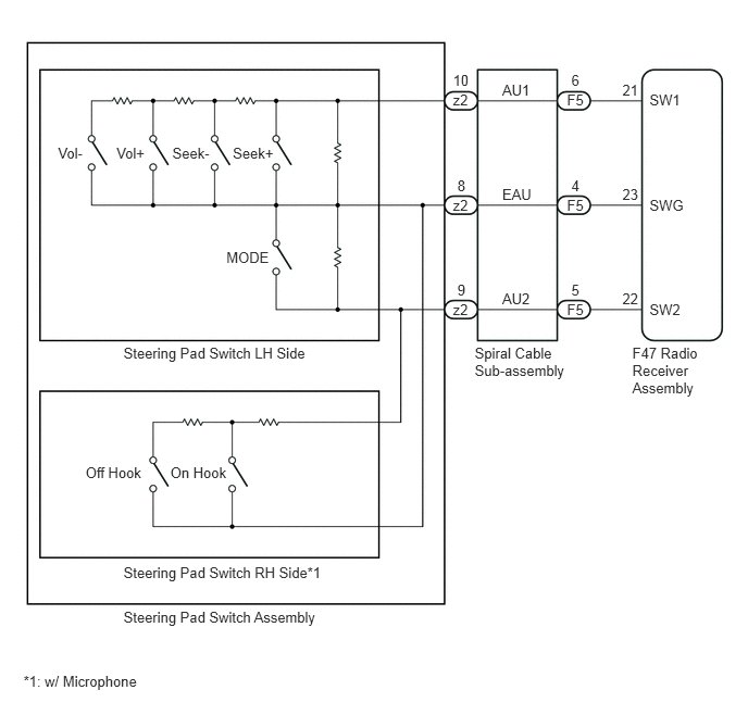
E226277E03
6.058,3.306 7.063,3.858 1.005,0.552 10 F47 Radio Receiver Assembly 4.548,3.306 5.493,3.844 0.945,0.538 10 Spiral Cable Sub-assembly 1.183,3.303 3.040,3.459 1.857,0.156 10 Steering Pad Switch LH Side 1.183,5.404 3.272,5.560 2.089,0.156 10 Steering Pad Switch RH Side*1 1.183,5.83 3.155,6.184 1.972,0.355 10 Steering Pad Switch Assembly 2.169,2.381 2.637,2.537 0.468,0.156 10 MODE 2.23,1.385 2.699,1.541 0.468,0.156 10 Seek+ 1.651,1.385 2.082,1.541 0.431,0.156 10 Seek- 1.116,1.385 1.454,1.541 0.339,0.156 10 Vol+ 1.632,4.45 2.246,4.626 0.614,0.176 10 On Hook 0.82,4.45 1.441,4.633 0.621,0.183 10 Off Hook 0.556,1.385 0.846,1.541 0.290,0.156 10 Vol- 5.432,2.883 5.718,3.038 0.286,0.154 10 F5 5.963,2.783 6.142,2.968 0.179,0.186 10 22 5.963,1.78 6.142,1.966 0.179,0.186 10 23 5.963,0.778 6.142,0.964 0.179,0.186 10 21 5.474,2.696 5.653,2.881 0.179,0.186 10 5 6.223,2.883 6.672,3.038 0.449,0.154 10 SW2 5.432,1.881 5.718,2.036 0.286,0.154 10 F5 5.474,1.694 5.653,1.879 0.179,0.186 10 4 6.223,1.881 6.672,2.036 0.449,0.154 10 SWG 5.432,0.879 5.718,1.034 0.286,0.154 10 F5 5.474,0.692 5.653,0.877 0.179,0.186 10 6 6.223,0.879 6.672,1.034 0.449,0.154 10 SW1 4.34,2.883 4.625,3.038 0.286,0.154 10 z2 4.382,2.696 4.561,2.881 0.179,0.186 10 9 4.812,2.786 5.261,2.941 0.449,0.154 10 AU2 4.34,1.881 4.625,2.036 0.286,0.154 10 z2 4.382,1.694 4.561,1.879 0.179,0.186 10 8 4.812,1.784 5.261,1.938 0.449,0.154 10 EAU 4.34,0.879 4.625,1.034 0.286,0.154 10 z2 4.34,0.692 4.519,0.877 0.179,0.186 10 10 4.812,0.782 5.261,0.936 0.449,0.154 10 AU1 0.225,6.45 2.315,6.606 2.089,0.156 10 *1: w/ Microphone

CAUTION / NOTICE / HINT

NOTICE:

The vehicle is equipped with an SRS (Supplemental Restraint System). Before servicing (including removal or installation of parts), be sure to read the precaution for Supplemental Restraint System (See page Vehicle Interior>SUPPLEMENTAL RESTRAINT SYSTEMS>AIRBAG SYSTEM(w/o VSC)>PRECAUTION).


PROCEDURE
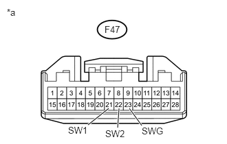
1.CHECK HARNESS AND CONNECTOR (STEERING PAD SWITCH SIGNAL)
a.
U158526E02
1.333,1.896 1.646,1.646 true 1.958,1.646 2.146,1.906 true 1.802,1.646 1.781,1.938 true 0.104,0.104 0.344,0.292 0.24,0.188 10 false *a 1.583,0.365 1.875,0.552 0.292,0.188 10 false F47 1.594,1.948 1.969,2.115 0.375,0.167 10 false SW2 2.146,1.906 2.521,2.073 0.375,0.167 10 false SWG 1.031,1.896 1.365,2.063 0.333,0.167 10 false SW1

Disconnect the F47 radio receiver assembly connector.


b.

Measure the resistance according to the value(s) in the table below.

Standard Resistance:
Tester Connection Switch Condition Specified Condition
F47-21 (SW1) - F47-23 (SWG) No switch pushed 95 to 105 kΩ
Seek+ switch pushed Below 2.5 Ω
Seek- switch pushed 313 to 345 Ω
Volume+ switch pushed 950 to 1050 Ω
Volume- switch pushed 2955 to 3265 Ω
F47-22 (SW2) - F47-23 (SWG) No switch pushed 95 to 105 kΩ
MODE switch pushed Below 2.5 Ω
On Hook switch pushed*1 313 to 345 Ω
Off Hook switch pushed*1 950 to 1050 Ω


*1: w/ Microphone


Text in Illustration
*a Front view of wire harness connector
(to Radio Receiver Assembly)


OK

PROCEED TO NEXT SUSPECTED AREA SHOWN IN PROBLEM SYMPTOMS TABLE

NG

2.INSPECT STEERING PAD SWITCH ASSEMBLY
a.

Inspect the steering pad switch assembly (See page Audio / Visual / Telematics>AUDIO / VIDEO>STEERING PAD SWITCH>INSPECTION).


OK

3.INSPECT SPIRAL CABLE SUB-ASSEMBLY

NG

REPLACE STEERING PAD SWITCH ASSEMBLY

3.INSPECT SPIRAL CABLE SUB-ASSEMBLY
a.

Inspect the spiral cable sub-assembly (See page Vehicle Interior>SUPPLEMENTAL RESTRAINT SYSTEMS>SPIRAL CABLE>INSPECTION).

NOTICE:

The spiral cable sub-assembly is an important part of the SRS airbag system. Incorrect removal or installation of the spiral cable sub-assembly may prevent the airbag from deploying. Refer to the pages shown in the brackets.


HINT:


OK

REPAIR OR REPLACE HARNESS OR CONNECTOR (RADIO RECEIVER ASSEMBLY - SPIRAL CABLE SUB-ASSEMBLY)

NG

REPLACE SPIRAL CABLE SUB-ASSEMBLY