RM19S0E
_58
Vehicle Interior
_051490
DOOR LOCK
_0248290
KEY REMINDER WARNING SYSTEM
U
DOOR LOCK KEY REMINDER WARNING SYSTEM TERMINALS OF ECU
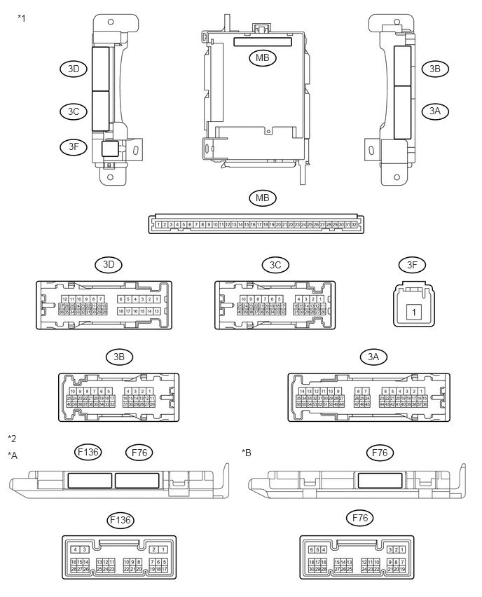
CHECK MAIN BODY ECU AND INSTRUMENT PANEL JUNCTION BLOCK ASSEMBLY
1.01,0.938 1.208,1.083
0.198,0.146
10
false
3D
0.26,0.188 0.406,0.333
0.146,0.146
10
false
*1
0.115,6.438 0.281,6.594
0.167,0.156
10
false
*2
1.531,3.844 1.729,3.99
0.198,0.146
10
false
3D
3.802,0.771 4.031,0.938
0.229,0.167
10
false
MB
3.802,2.854 4.031,3.01
0.229,0.156
10
false
MB
1.01,1.573 1.208,1.729
0.198,0.156
10
false
3C
4.01,3.854 4.219,4
0.208,0.146
10
false
3C
6.385,0.938 6.583,1.083
0.198,0.146
10
false
3B
6.385,1.563 6.583,1.708
0.198,0.146
10
false
3A
5.469,5.219 5.667,5.365
0.198,0.146
10
false
3A
5.531,6.646 5.792,6.792
0.26,0.146
10
false
F76
5.24,7.615 5.51,7.76
0.271,0.146
10
false
F76
1.688,5.219 1.885,5.365
0.198,0.146
10
false
3B
1.021,2.094 1.219,2.25
0.198,0.156
10
false
3F
6.052,3.854 6.24,4
0.188,0.146
10
false
3F
0.115,6.688 0.281,6.844
0.167,0.156
10
false
*A
3.594,6.646 3.76,6.802
0.167,0.156
10
false
*B
1.958,6.646 2.219,6.792
0.26,0.146
10
false
F76
1.156,6.635 1.51,6.781
0.354,0.146
10
false
F136
1.635,7.646 1.99,7.792
0.354,0.146
10
false
F136
| *A | Main Body ECU 2 Connector Type | *B | Main Body ECU 1 Connector Type |
| *1 | Instrument Panel Junction Block Assembly | *2 | Main Body ECU |
a.
Remove the main body ECU from the instrument panel junction block assembly (See page Power Source / Network>POWER DISTRIBUTION>MAIN BODY ECU>REMOVAL).
b.
Disconnect the F76 main body ECU connector.
c.
Measure the voltage and resistance according to the value(s) in the table below.
| Terminal No. (Symbol) | Wiring Color | Terminal Description | Condition | Specified Condition |
|---|---|---|---|---|
| MB-11 (GND1) - Body ground | None - Body ground | Ground | Always | Below 1 Ω |
| MB-30 (BECU) - Body ground | None - Body ground | Battery power supply | Always | 11 to 14 V |
| MB-29 (ACC) - Body ground | None - Body ground | ACC power supply | Ignition switch on (ACC) | 11 to 14 V |
| MB-32 (IG) - Body ground | None - Body ground | Ignition switch power supply | Ignition switch on (IG) | 11 to 14 V |
| F76-17 (KSW) - Body ground | Y - Body ground | Unlock warning switch input | No Key in ignition key cylinder (off) | 10 kΩ or higher |
| Key inserted ignition key cylinder (on) | Below 1 Ω |
d.
Install the main body ECU to the instrument panel junction block assembly (See page Power Source / Network>POWER DISTRIBUTION>MAIN BODY ECU>INSTALLATION).
e.
Reconnect the F76 main body ECU connector.
f.
Measure the voltage and check for pulse according to the value(s) in the table below.
| Terminal No. (Symbol) | Wiring Color | Terminal Description | Condition | Specified Condition |
|---|---|---|---|---|
| F76-19 (FRCY) - Body ground | Y - Body ground | Front door RH courtesy light switch input | Front door RH open | Below 1 V |
| Front door RH closed | Pulse generation | |||
| F76-17 (KSW) - Body ground | Y - Body ground | Unlock warning switch input | No Key in ignition key cylinder (off) | 11 to 14 V |
| Key inserted ignition key cylinder (on) | Below 1 V |