LIGHTING (EXT) AUTOMATIC HEADLIGHT BEAM LEVEL CONTROL SYSTEM B241A Rear Height Control Sensor
DESCRIPTION
The headlight leveling ECU assembly receives signals indicating the height of the vehicle from the rear height control sensor sub-assembly.
| DTC No. | DTC Detecting Condition | Trouble Area |
|---|---|---|
| B241A | ·
Malfunction in rear height control sensor sub-assembly ·
Open or short in rear height control sensor sub-assembly circuit |
·
Rear height control sensor sub-assembly ·
Harness or connector ·
Headlight leveling ECU assembly |
WIRING DIAGRAM
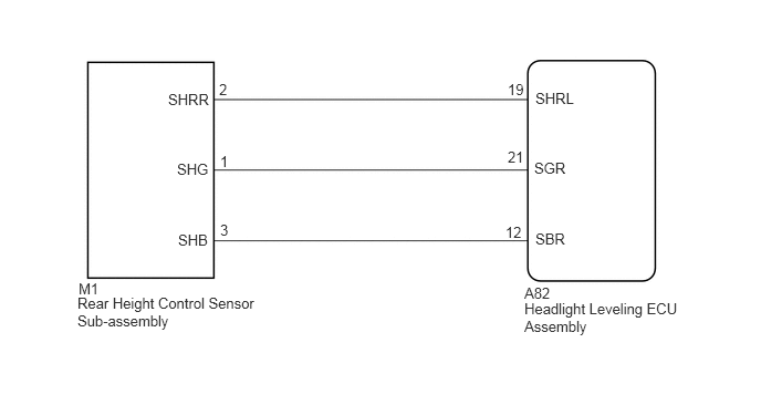
CAUTION / NOTICE / HINT
- NOTICE:
-
If either of the following is performed, initialization of the headlight leveling ECU assembly is necessary (See page Vehicle Exterior>LIGHTING (EXT)>AUTOMATIC HEADLIGHT BEAM LEVEL CONTROL SYSTEM>INITIALIZATION).
- ·
Replacement of the headlight leveling ECU assembly.
·Replacement or removal/installation of the rear height control sensor sub-assembly or work that changes the vehicle height such as replacement of suspension components.
PROCEDURE
Clear the DTCs (See page Vehicle Exterior>LIGHTING (EXT)>AUTOMATIC HEADLIGHT BEAM LEVEL CONTROL SYSTEM>DTC CHECK / CLEAR).
Check for DTCs (See page Vehicle Exterior>LIGHTING (EXT)>AUTOMATIC HEADLIGHT BEAM LEVEL CONTROL SYSTEM>DTC CHECK / CLEAR).
- OK:
DTC B241A is not output
OK
(See pageGeneral>INTRODUCTION>HOW TO TROUBLESHOOT ECU CONTROLLED SYSTEMS>HOW TO PROCEED WITH TROUBLESHOOTING)
NG
Connect the GTS to the DLC3.
Turn the ignition switch to ON.
Turn the GTS on.
Enter the following menus: Body Electrical / HL Auto Leveling / Data List.
Read the display on the GTS.
| Tester Display | Measurement Item/Range | Normal Condition | Diagnostic Note |
|---|---|---|---|
| Height Sens Pw Supply Val | Rear height control sensor power supply value / 0.00 to 5.00 V | Approx. 5 V | - |
| Rr Height Sens Signal Val | Rear height control sensor signal value / 0.00 to 5.00 V | Approx. 2.5 V (When the vehicle is level) | Value changes according to vehicle height |
- OK:
Normal conditions listed above are displayed.
OK
NG
Remove the rear height control sensor sub-assembly (See page Vehicle Exterior>LIGHTING (EXT)>HEIGHT CONTROL SENSOR>REMOVAL).
Inspect the rear height control sensor sub-assembly (See page Vehicle Exterior>LIGHTING (EXT)>HEIGHT CONTROL SENSOR>INSPECTION).
OK
NG
Disconnect the A82 headlight leveling ECU assembly connector.
Disconnect the M1 rear height control sensor sub-assembly connector.
Measure the resistance according to the value(s) in the table below.
- Standard Resistance:
Tester Connection Condition Specified Condition A82-19 (SHRL) - M1-2 (SHRR) Always Below 1 Ω A82-19 (SHRL) or M1-2 (SHRR) - Body ground Always 10 kΩ or higher
OK
NG