HEATING / AIR CONDITIONING CONDENSER INSTALLATION
PROCEDURE

 88460
1.INSTALL COOLER CONDENSER ASSEMBLY
Engage the 2 claws, 2 guides and install the cooler condenser into the vehicle.
- NOTICE:
-
Do not damage the condenser or radiator when installing the condenser.
- HINT:
-
If a new cooler condenser is installed, add compressor oil to the condenser as follows.
- Capacity:
Add 40 cc (1.35 fl. oz.)
- Compressor oil:
ND-OIL8 or equivalent.
88706A
2.CONNECT LIQUID TUBE SUB-ASSEMBLY A
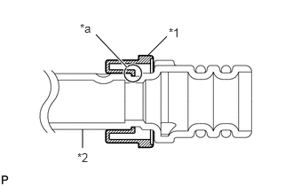
| *1 | Piping Clamp |
| *2 | Liquid Tube Sub-assembly A |
| *a | Groove |
Install a new piping clamp to the liquid tube sub-assembly A.
- NOTICE:
-
Securely engage the inside step of the piping clamp in the liquid tube sub-assembly A groove.
Remove the vinyl tape from the open ends of the liquid tube sub-assembly A and cooler condenser assembly.
Thoroughly coat a new O-ring and contact surface of the liquid tube sub-assembly A with compressor oil.
- Compressor oil:
ND-OIL8 or equivalent.
Install the 2 O-rings to the liquid tube sub-assembly A.
- NOTICE:
-
Do not let foreign matter adhere to the O-ring or O-ring seal.
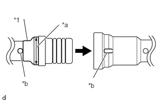
| *1 | Liquid Tube Sub-assembly A |
| *a | Large Diameter Section of Piping Clamp |
| *b | Alignment Mark |
Connect the liquid tube sub-assembly A and cooler condenser assembly by matching the alignment marks.
- NOTICE:
-
Insert them by holding the pipe, not the piping clamp.
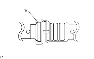
| *a | Large Diameter Section of Piping Clamp |
Securely insert the piping clamp to the point where the large diameter section of the piping clamp is covered by the liquid tube sub-assembly A.
- HINT:
- ·
When inserting, make sure that a click sound is heard.
·Check that the liquid tube sub-assembly A is securely inserted by pulling it.
88711
3.CONNECT NO. 1 COOLER REFRIGERANT DISCHARGE HOSE
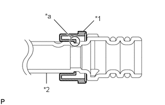
| *1 | Piping Clamp |
| *2 | No. 1 Cooler Refrigerant Discharge Hose |
| *a | Groove |
Install a new piping clamp to the No. 1 cooler refrigerant discharge hose.
- NOTICE:
-
Securely engage the inside step of the piping clamp in the No. 1 cooler refrigerant discharge hose groove.
Remove the vinyl tape from the open ends of the No. 1 cooler refrigerant discharge hose and cooler condenser assembly.
Thoroughly coat a new O-ring and contact surface of the No. 1 cooler refrigerant discharge hose with compressor oil.
- Compressor oil:
ND-OIL8 or equivalent.
Install the 2 O-rings to the No. 1 cooler refrigerant discharge hose.
- NOTICE:
-
Do not let foreign matter adhere to the O-ring or O-ring seal.
| *1 | No. 1 Cooler Refrigerant Discharge Hose |
| *a | Large Diameter Section of Piping Clamp |
| *b | Alignment Mark |
Connect the No. 1 cooler refrigerant discharge hose and cooler condenser assembly by matching the alignment marks.
- NOTICE:
-
Insert them by holding the pipe, not the piping clamp.
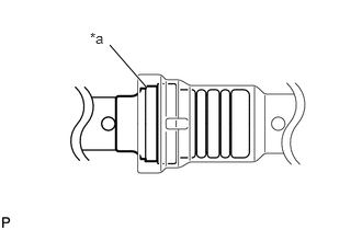
| *a | Large Diameter Section of Piping Clamp |
Securely insert the piping clamp to the point where the large diameter section of the piping clamp is covered by the No. 1 cooler refrigerant discharge hose.
- HINT:
- ·
When inserting, make sure that a click sound is heard.
·Check that the No. 1 cooler refrigerant discharge hose is securely inserted by pulling it.
88891H
4.INSTALL NO. 1 COOLER COVER
Engage the 2 guides and install the cooler cover.
53205
5.INSTALL RADIATOR UPPER SUPPORT SUB-ASSEMBLY
Install the radiator upper support with the 4 bolts.
- Torque:
- 5.5 N*m (56 kgf*cm, 49 in.*lbf)
Engage the 2 clamps and install the hood lock control cable.
Engage the 2 clamps and install the wire harness.
Connect the connector.
Install the 2 clips.
89173
6.INSTALL FRONT AIRBAG SENSOR
7.INSTALL HEADLIGHT ASSEMBLY LH
8.INSTALL HEADLIGHT ASSEMBLY RH
- HINT:
-
Use the same procedure as for the LH side.
9. CHARGE REFRIGERANT
10. WARM UP ENGINE
11.INSPECT FOR REFRIGERANT LEAK