Home › Steering › STEERING COLUMN › STEERING COLUMN ASSEMBLY (for Hatchback)

STEERING COLUMN ASSEMBLY (for Hatchback) > INSTALLATION


1. INSTALL STEERING COLUMN ASSEMBLY
  1. Install the steering column assembly to the instrument panel reinforcement assembly with the 2 nuts and the bolt.

    Torque:
    Bolt:
    36 N*m{ 367 kgf*cm , 27 ft.*lbf }
    Nut:
    25 N*m{ 255 kgf*cm , 18 ft.*lbf }

    NOTICE:
    Be sure there is no interference around the wire harness.

  1. Connect all the connectors and engage all the wire harness clamps to the steering column assembly bracket.

  1. Install the wire harness clamp to the power steering ECU assembly.

  1. Connect the 2 steering column assembly connectors to the power steering ECU assembly.


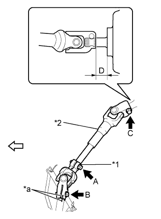
2. INSTALL STEERING SLIDING YOKE SUB-ASSEMBLY


    C236725E03
  1. Tighten the bolt C while aligning the No. 2 steering intermediate shaft assembly with the position D as shown in the illustration.
    Text in Illustration 
    *1
    Steering Sliding Yoke Sub-assembly
    *2
    No. 2 Steering Intermediate Shaft Assembly
    *a
    Matchmark
    V100136
    Front of the Vehicle

    Standard D:
    18.5 to 19.7 mm (0.728 to 0.776 in.)

    Torque:
    35 N*m{ 360 kgf*cm , 26 ft.*lbf }

  1. Align the matchmarks on the steering sliding yoke sub-assembly and the steering gear assembly.

    HINT:
    When the steering sliding yoke sub-assembly is replaced with a new one, it has no matchmarks, so install it while the head of the bolt B faces the back of the vehicle as shown in the illustration.

  1. Install bolt B.

    Torque:
    35 N*m{ 360 kgf*cm , 26 ft.*lbf }

  1. Tighten bolt A.

    Torque:
    35 N*m{ 360 kgf*cm , 26 ft.*lbf }


3. INSTALL COLUMN HOLE COVER SILENCER SHEET
  1. Install the column hole cover silencer sheet with the 2 clips.

  1. Install the floor carpet.


4. INSTALL BRAKE PEDAL SUPPORT SUB-ASSEMBLY
(Click here)


5. INSTALL COMBINATION SWITCH ASSEMBLY
  1. Install the combination switch assembly to the steering column assembly with the clamp.

  1. Connect all the connectors to the combination switch assembly.


6. INSTALL UPPER STEERING COLUMN COVER
  1. Engage the claw to install the upper steering column cover.


7. INSTALL LOWER STEERING COLUMN COVER
  1. Engage the 4 claws to install the lower steering column cover.

  1. Install the 3 screws.


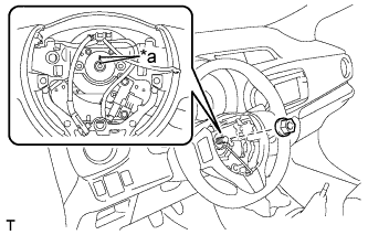
8. INSTALL STEERING WHEEL ASSEMBLY


    C241422E01
  1. Align the matchmarks and install the steering wheel assembly onto the steering column assembly.
    Text in Illustration 
    *a
    Matchmark

  1. Install the steering wheel assembly set nut.

    Torque:
    50 N*m{ 510 kgf*cm , 37 ft.*lbf }

  1. Connect the connectors to the spiral cable sub-assembly.


9. INSTALL STEERING PAD
(Click here)


10. POSITION FRONT WHEELS FACING STRAIGHT AHEAD


11. CONNECT CABLE TO NEGATIVE BATTERY TERMINAL

Torque:
5.4 N*m{ 55 kgf*cm , 48 in.*lbf }


12. INSPECT SRS WARNING LIGHT
(Click here)


13. PERFORM CALIBRATION OF TORQUE SENSOR ZERO POINT
(Click here)