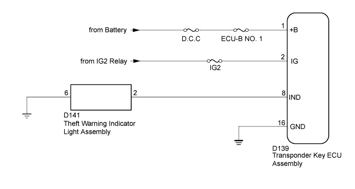
ENGINE IMMOBILISER SYSTEM (for Hatchback) > Security Indicator Light Does not Blink |
| 1.CHECK FOR DTC |
Check for DTCs (Click here).
|
| ||||
| OK | |
 |
| 2.PERFORM ACTIVE TEST USING TECHSTREAM (SECURITY INDICATOR) |
Check that the theft warning indicator light assembly illuminates when operating it with the Active Test (Click here).
| Tester Display | Test Part | Control Range | Diagnostic Note |
| Security Indicator | Theft Warning Indicator Light Assembly | OFF / ON | - |
|
| ||||
| OK | |
|
| 3.READ VALUE USING TECHSTREAM (ENGINE IMMOBILISER SYSTEM STATUS) |
Turn the ignition switch off.
Using the Techstream, read the Data List (Click here).
| Tester Display | Measurement Item/Range | Normal Condition | Diagnostic Note |
| Immobiliser | Engine immobiliser system status determined by transponder key ECU assembly / Set or Unset | Set: Engine immobiliser set (engine start prohibited (no key in ignition key cylinder)) Unset: Engine immobiliser unset (engine start permitted (key inserted in ignition key cylinder)) | When the engine immobiliser system does not change to the unset state, this item can be used to determine if the cause is the transponder key ECU assembly. |
|
| ||||
| OK | ||
 | ||
| ||
| 4.CHECK HARNESS AND CONNECTOR (TRANSPONDER KEY ECU ASSEMBLY - THEFT WARNING INDICATOR LIGHT ASSEMBLY AND BODY GROUND) |
Disconnect the D139 transponder key ECU assembly connector.
Disconnect the D141 theft warning indicator light assembly connector.
Measure the resistance according to the value(s) in the table below.
| Tester Connection | Condition | Specified Condition |
| D139-8 (IND) - D141-2 | Always | Below 1 Ω |
| D141-6 - Body ground | Always | Below 1 Ω |
| D139-8 (IND) - Body ground | Always | 10 kΩ or higher |
|
| ||||
| OK | |
|
| 5.INSPECT THEFT WARNING INDICATOR LIGHT ASSEMBLY |
Inspect the theft warning indicator light assembly (Click here).
|
| ||||
| OK | ||
| ||
| ||
| 6.CHECK HARNESS AND CONNECTOR (TRANSPONDER KEY ECU ASSEMBLY - BATTERY AND BODY GROUND) |
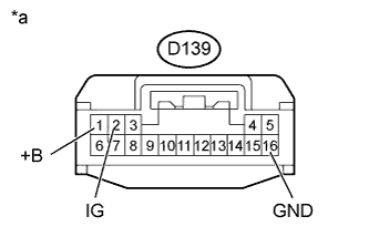 |
Disconnect the D139 transponder key ECU assembly connector.
Measure the resistance according to the value(s) in the table below.
| Tester Connection | Condition | Specified Condition |
| D139-16 (GND) - Body ground | Always | Below 1 Ω |
Measure the voltage according to the value(s) in the table below.
| Tester Connection | Switch Condition | Specified Condition |
| D139-1 (+B) - Body ground | Always | 11 to 14 V |
| D139 (IG) - Body ground | Ignition switch off | Below 1 V |
| Ignition switch ON | 11 to 14 V |
| *a | Front view of wire harness connector (to Transponder Key ECU Assembly) |
|
| ||||
| OK | ||
| ||
| ||

