 |
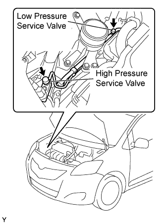
Remove the caps from the service valves on the refrigerant line.
AIR CONDITIONING UNIT (for Sedan) > REMOVAL |
| 1. PRECAUTION |
| 2. DISCONNECT CABLE FROM NEGATIVE BATTERY TERMINAL |
| 3. RECOVER REFRIGERANT FROM REFRIGERATION SYSTEM |
Start up the engine.
Switch A/C ON.
Turn the blower switch to ON.
Operate the cooler compressor with an engine speed of approximately 1,000 rpm for 5 to 6 minutes to circulate the refrigerant and collect the remaining compressor oil from each component, in the cooler compressor.
Stop the engine.
|
Remove the caps from the service valves on the refrigerant line.
Connect the refrigerant recovery unit.
Recover the refrigerant from the air conditioning system using a refrigerant recovery unit.
| 4. DRAIN ENGINE COOLANT |
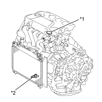 |
Loosen the radiator drain cock plug.
| *1 | Water Filler Cap Sub-assembly |
| *2 | Radiator Drain Cock Plug |
Remove the water filler cap sub-assembly, then drain coolant.
| 5. DISCONNECT SUCTION TUBE SUB-ASSEMBLY |
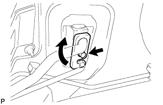 |
Remove the bolt.
Turn the hook type connector clockwise and disconnect the suction tube sub-assembly.
Remove the O-ring from the suction tube sub-assembly.
| 6. DISCONNECT LIQUID TUBE SUB-ASSEMBLY |
Disconnect the liquid tube sub-assembly.
Remove the O-ring from the liquid tube sub-assembly.
| 7. DISCONNECT HEATER WATER OUTLET HOSE |
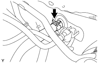 |
Using pliers, grip the claws of the clip, slide the clip and disconnect the heater water outlet hose from the heater unit.
| 8. DISCONNECT HEATER WATER INLET HOSE |
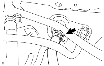 |
Using pliers, grip the claws of the clip, slide the clip and disconnect the heater water inlet hose from the heater unit.
| 9. REMOVE LOWER INSTRUMENT PANEL SUB-ASSEMBLY |
| 10. REMOVE STEERING COLUMN ASSEMBLY |
| 11. REMOVE HEATER TO REGISTER DUCT ASSEMBLY |
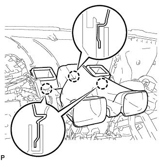 |
Disengage the 3 claws to remove the heater to register duct assembly.
| 12. REMOVE DEFROSTER NOZZLE ASSEMBLY |
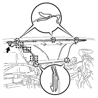 |
Disconnect the connector and 3 clamps.
Disengage the 5 claws to remove the defroster nozzle assembly.
| 13. REMOVE INSTRUMENT PANEL BRACE SUB-ASSEMBLY |
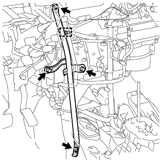 |
Disengage the clamp.
Remove the 2 bolts, screw, nut and the instrument panel brace sub-assembly.
| 14. SEPARATE MAIN BODY ECU (DRIVER SIDE J/B) |
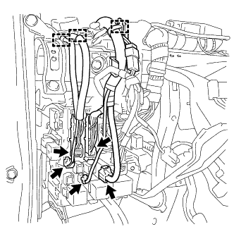 |
Disconnect the 5 connectors and the 3 clamps.
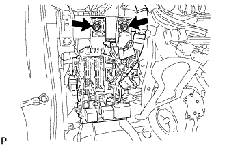 |
Remove the 2 bolts to separate the main body ECU.
| 15. SEPARATE CONNECTOR NO. 2 HOLDER |
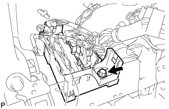 |
Remove the bolt.
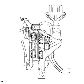 |
Disconnect the connectors to separate the connector No. 2 holder.
| 16. REMOVE INSTRUMENT PANEL REINFORCEMENT |
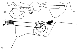 |
Disconnect the drain hose.
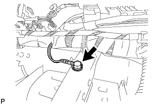 |
Remove the bolt to disconnect the ground wire.
Disconnect the connectors.
Disengage the clamps.
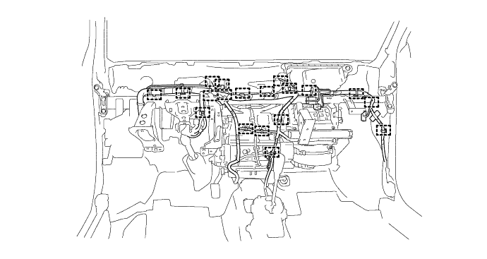
Disconnect the connectors and clamps.
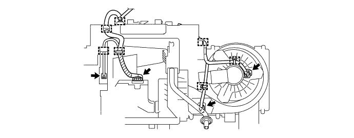
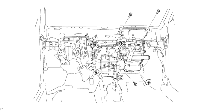
Remove the 3 bolts and the nut.
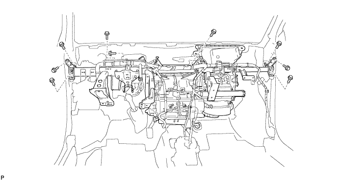
Remove the 9 bolts and the instrument panel reinforcement together with the air conditioning unit.
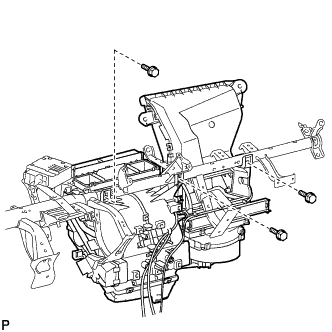 |
Remove the 3 screws and the air conditioning unit.
| 17. REMOVE AIR CONDITIONING AMPLIFIER ASSEMBLY |
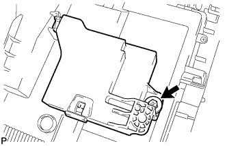 |
Remove the screw and the air conditioning amplifier assembly.
| 18. REMOVE AIR CONDITIONING UNIT |
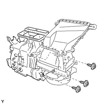 |
Remove the 3 screws and the air conditioning unit.