| B |  |
| GO TO DIAGNOSTIC TROUBLE CODE CHART (Click here) |
METER / GAUGE SYSTEM (for Hatchback) > Fuel Receiver Gauge Malfunction |
| 1.CONFIRM DTC OUTPUT |
Check DTC (Click here).
| Result | Proceed to |
| DTC B1500 is not output | A |
| DTC B1500 is output | B |
|
| ||||
| A | |
 |
| 2.PERFORM ACTIVE TEST USING TECHSTREAM (FUEL METER OPERATION) |
Connect the Techstream to the DLC3.
Turn the ignition switch to ON.
Turn the Techstream on.
Enter the following menus: Body Electrical / Combination Meter / Active Test.
According to the display on the Techstream, perform the Active Test.
| Tester Display | Test Part | Control Range | Diagnostic Note |
| Fuel Meter Operation | Fuel gauge | EMPTY / 1/2 / FULL | Vehicle is stopped and the engine idling |
|
| ||||
| OK | |
|
| 3.INSPECT FUEL SENDER GAUGE ASSEMBLY |
Remove the fuel sender gauge assembly (Click here).
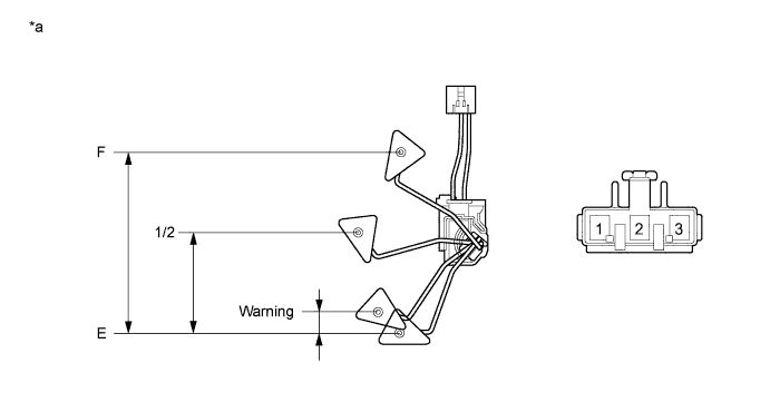
| *a | Component without harness connected (Fuel Sender Gauge Assembly) | - | - |
Check that the float moves smoothly between F and E.
Measure the resistance according to the value(s) in the table below.
| Tester Connection | Float Level | Float Position (mm (in.)) | Specified Condition |
| 1 - 2 | F | 142 to 152 (5.591 to 5.984) | 13.5 to 16.5 Ω |
| 1/2 | 71.1 to 76.1 (2.799 to 2.996) | 208.3 Ω | |
| Warning | 5.9 to 10.9 (0.232 to 0.429) | 365.2 Ω | |
| E | 0 (0) | 405.5 to 414.5 Ω |
Reinstall the fuel sender gauge assembly.
|
| ||||
| OK | |
|
| 4.CHECK FUEL SUCTION WITH PUMP AND GAUGE TUBE ASSEMBLY |
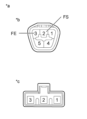 |
Remove the fuel suction with pump and gauge tube assembly .
Measure the resistance according to the value(s) in the table below.
| Tester Connection | Condition | Specified Condition |
| A-2 (FS) - B-2 | Always | Below 1 Ω |
| A-3 (FE) - B-1 | Always | Below 1 Ω |
| *a | Component without harness connected (Fuel Suction with Pump and Gauge Tube Assembly) |
| *b | Connector A |
| *c | Connector B |
Reinstall the fuel suction plate sub-assembly.
|
| ||||
| OK | |
|
| 5.CHECK HARNESS AND CONNECTOR (COMBINATION METER ASSEMBLY - FUEL SUCTION WITH PUMP AND GAUGE TUBE ASSEMBLY) |
Disconnect the D100 combination meter assembly connector.
Disconnect the J71 fuel suction with pump and gauge tube assembly connector.
Measure the resistance according to the value(s) in the table below.
| Tester Connection | Condition | Specified Condition |
| D100-16 (L) - J71-2 (FS) | Always | Below 1 Ω |
| D100-16 (L) - Body ground | Always | 10 kΩ or higher |
| J71-3 (FE) - Body ground | Always | Below 1 Ω |
Reconnect the fuel suction with pump and gauge tube assembly connector.
Reconnect the combination meter assembly connector.
|
| ||||
| OK | ||
 | ||
| ||