 |
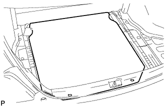
Remove the spare wheel cover assembly.
ROOF HEADLINING (for Sedan) > REMOVAL |
| 1. REMOVE FRONT SEAT ASSEMBLY LH |
| 2. REMOVE FRONT SEAT ASSEMBLY RH |
| 3. REMOVE REAR SEAT ASSEMBLY LH |
| 4. REMOVE REAR SEAT ASSEMBLY RH |
| 5. REMOVE SPARE WHEEL COVER ASSEMBLY |
|
Remove the spare wheel cover assembly.
| 6. REMOVE LUGGAGE COMPARTMENT TRIM INNER PAD |
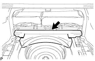 |
Remove the luggage compartment trim inner pad.
| 7. REMOVE FRONT DOOR SCUFF PLATE RH |
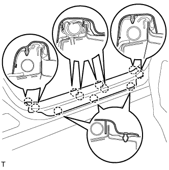 |
Disengage the 11 claws and remove the front door scuff plate.
| 8. REMOVE FRONT DOOR SCUFF PLATE LH |
| 9. REMOVE COWL SIDE TRIM BOARD RH |
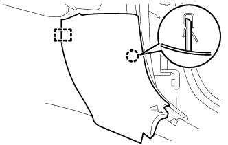 |
Disengage the claw and the stud bolt and remove the cowl side trim board.
| 10. REMOVE COWL SIDE TRIM BOARD LH |
| 11. REMOVE FRONT DOOR OPENING TRIM WEATHERSTRIP RH |
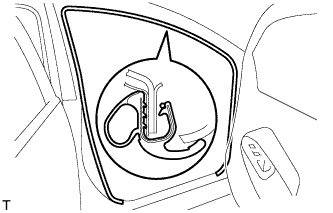 |
Remove the front door opening trim weatherstrip.
| 12. REMOVE FRONT DOOR OPENING TRIM WEATHERSTRIP LH |
| 13. REMOVE REAR DOOR SCUFF PLATE RH |
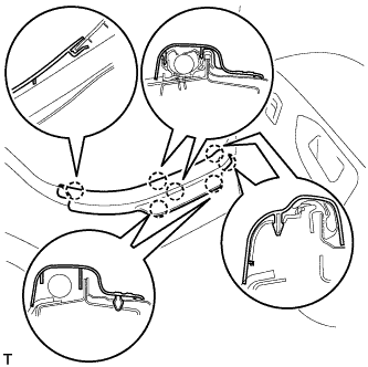 |
Disengage the 7 claws and remove the rear door scuff plate.
| 14. REMOVE REAR DOOR SCUFF PLATE LH |
| 15. REMOVE REAR DOOR OPENING TRIM WEATHERSTRIP RH |
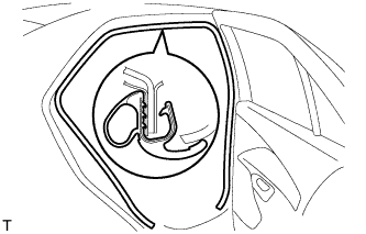 |
Remove the rear door opening trim weatherstrip.
| 16. REMOVE REAR DOOR OPENING TRIM WEATHERSTRIP LH |
| 17. REMOVE REAR SEAT SIDE COVER RH |
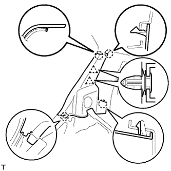 |
Disengage the 2 clips and the 4 claws and remove the rear seat side cover.
| 18. REMOVE REAR SEAT SIDE COVER LH |
| 19. REMOVE ROOF SIDE INNER GARNISH RH |
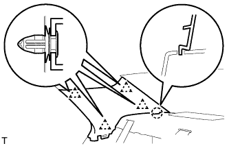 |
Disengage the 4 clips and the claw and remove the roof side inner garnish.
| 20. REMOVE ROOF SIDE INNER GARNISH LH |
| 21. REMOVE CENTER PILLAR LOWER GARNISH RH |
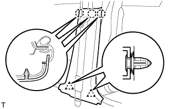 |
Disengage the 3 claws and 2 clips and remove the center pillar lower garnish.
| 22. REMOVE CENTER PILLAR LOWER GARNISH LH |
| 23. REMOVE SEAT BELT ANCHOR COVER CAP |
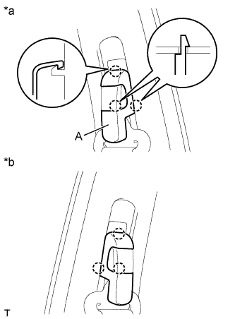 |
Pull portion A, shown in the illustration, toward you, disengage the 2 claws on the lower side followed by the claw on the upper side. Then remove the seat belt anchor cover cap.
| *a | for RH Side |
| *b | for LH Side |
| 24. REMOVE FRONT SEAT OUTER BELT ASSEMBLY RH |
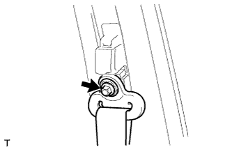 |
Remove the bolt and the through anchor.
| 25. REMOVE FRONT SEAT OUTER BELT ASSEMBLY LH |
| 26. REMOVE CENTER PILLAR UPPER GARNISH RH |
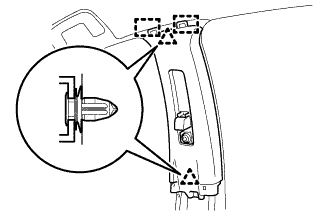 |
Disengage the 2 clips and 2 hooks and remove the center pillar upper garnish.
| 27. REMOVE CENTER PILLAR UPPER GARNISH LH |
| 28. REMOVE FRONT PILLAR GARNISH RH |
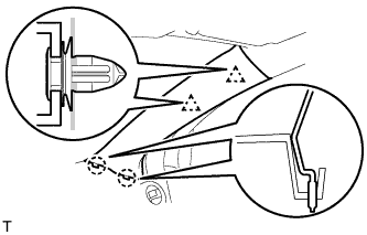 |
Disengage the 2 clips and the 2 claws and remove the front pillar garnish.
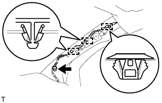 |
Disconnect the antenna connector.
Using a clip remover, remove the 3 clamps.
| 29. REMOVE FRONT PILLAR GARNISH LH |
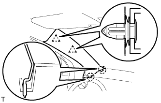 |
Disengage the 2 clips and the 2 claws and remove the front pillar garnish.
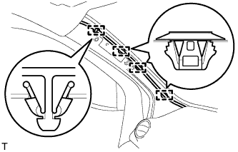 |
Using a clip remover, remove the 4 clamps.
| 30. REMOVE REAR CONSOLE BOX ASSEMBLY |
| 31. REMOVE UPPER INSTRUMENT PANEL SUB-ASSEMBLY |
| 32. REMOVE INSTRUMENT PANEL BOX |
Open the instrument panel box.
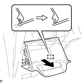 |
Pull the instrument panel box out horizontally with the instrument panel open and disengage the 2 hinges.
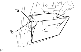 |
Remove the stopper of the instrument panel box from the cutout of the lower instrument panel and remove the instrument panel box.
| *a | Stopper |
| *b | Cutout |
| 33. REMOVE ASSIST GRIP COVER |
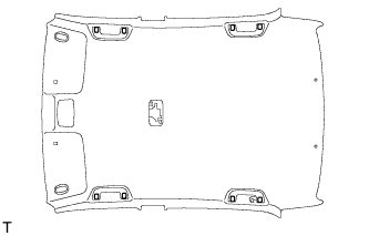 |
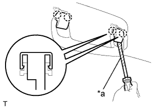 |
Using a screwdriver with its tip wrapped in protective tape, disengage the 2 claws and remove the assist grip cover.
| *a | Protective Tape |
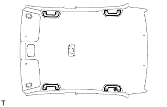
| 34. REMOVE ASSIST GRIP SUB-ASSEMBLY |
 |
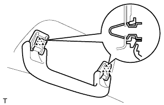 |
Disengage the 2 clips and remove the assist grip.
| 35. REMOVE VISOR ASSEMBLY RH |
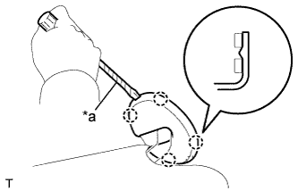 |
Using a screwdriver with its tip wrapped in protective tape, disengage the 4 claws and remove the visor bracket cover.
| *a | Protective Tape |
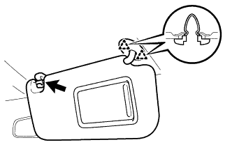 |
Remove the visor shaft from the visor holder.
Disengage the 2 clips and remove the visor.
| 36. REMOVE VISOR ASSEMBLY LH |
| 37. REMOVE VISOR HOLDER RH |
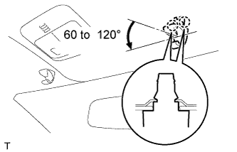 |
Disengage the 2 claws by turning the visor holder counterclockwise between 60 to 120° and remove the visor holder.
| 38. REMOVE VISOR HOLDER LH |
| 39. REMOVE ROOM LIGHT ASSEMBLY |
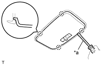 |
Using a screwdriver with its tip wrapped in protective tape, disengage the 4 claws and remove the room light lens.
| *a | Protective Tape |
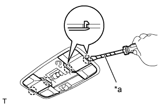 |
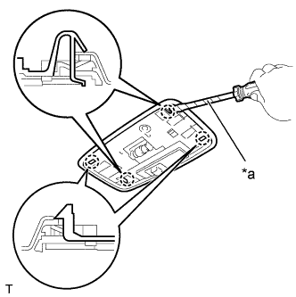
Using a screwdriver with its tip wrapped in protective tape, disengage the 2 claws and remove the cover.
| *a | Protective Tape |
 |
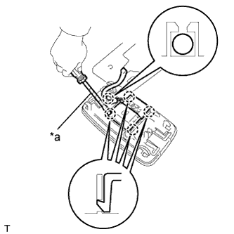
Using a screwdriver with its tip wrapped in protective tape, disengage the 4 claws and remove the room light holder.
| *a | Protective Tape |
 |
Remove the roof wire from the claw of the room light holder.
| *a | Protective Tape |
Using a screwdriver with its tip wrapped in protective tape, disengage the 4 claws and disconnect the room light switch base.
| 40. REMOVE MAP LIGHT ASSEMBLY |
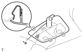 |
Using a moulding remover, disengage the 4 claws and remove the map light.
| *a | Molding Remover |
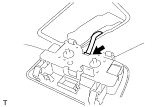 |
Disconnect the map light connector.
| 41. REMOVE ROOF HEADLINING ASSEMBLY |
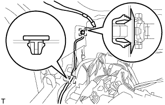 |
Using a clip remover, remove the 2 clamps.
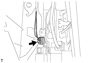 |
Disconnect the roof wire connector.
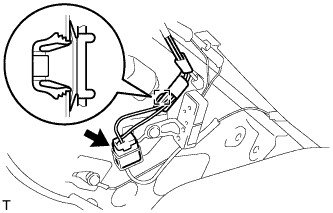 |
Using a clip remover, remove the clamp.
Disconnect the antenna connector.
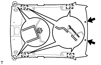 |
Using a clip remover, remove the 2 clips.
Disengage the 2 claws and 4 hooks.
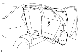 |
Remove the roof headlining from the front door.