 |
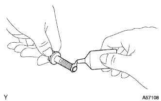
Apply adhesive to 2 or 3 threads on the end of the 4 bolts.
- Adhesive:
- Toyota Genuine Adhesive 1324, Three Bond 1324 or equivalent.
MANUAL TRANSAXLE ASSEMBLY (for Hatchback) > INSTALLATION |
| 1. INSTALL WIRE HARNESS CLAMP BRACKET |
Install the 3 wire harness clamp brackets with 3 bolts onto the manual transaxle assembly.
| 2. INSTALL SPEEDOMETER DRIVEN HOLE COVER SUB-ASSEMBLY (w/ ABS) |
Coat a new O-ring with manual transaxle gear oil and install it onto the speedometer driven hole cover sub-assembly.
Install the speedometer driven hole cover sub-assembly with the bolt.
| 3. INSTALL SPEEDOMETER SENSOR (w/o ABS) |
Coat a new O-ring with manual transaxle gear oil and install it onto the speedometer sensor.
Install the speedometer driven gear into the speedometer sensor with the E-ring.
Install the speedometer sensor with the bolt.
| 4. INSTALL MANUAL TRANSAXLE ASSEMBLY |
Align the input shaft with the clutch disc and install the manual transaxle assembly onto the engine.
Install the 7 bolts.
| 5. INSTALL TRANSVERSE ENGINE ENGINE MOUNTING BRACKET |
Remove any adhesive remaining in the 4 bolts holes on the transverse engine engine mounting bracket and 4 bolts.
|
Apply adhesive to 2 or 3 threads on the end of the 4 bolts.
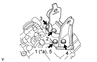 |
Following the procedures shown in the illustration, Tighten the 4 bolts in order.
| *a | Temporarily |
| 6. INSTALL TRANSVERSE ENGINE ENGINE MOUNTING INSULATOR |
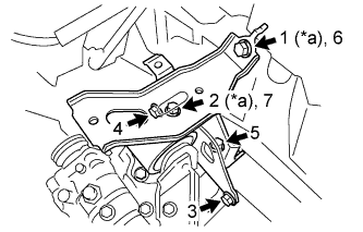 |
Following the procedures shown in the illustration, Tighten the 5 bolts in order.
Install the transverse engine engine mounting bracket and transverse engine engine mounting insulator with the bolt and nut.
| 7. INSTALL TRANSVERSE ENGINE ENGINE MOUNTING CONTROL BRACKET |
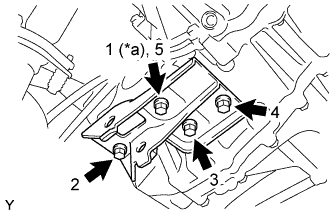 |
Following the procedures shown in the illustration, tighten the 4 bolts in order.
| *a | Temporarily |
| 8. INSTALL FRONT SUSPENSION CROSSMEMBER SUB-ASSEMBLY |
| 9. INSTALL STARTER ASSEMBLY (for Cold Area Specification Vehicles) |
| 10. INSTALL STARTER ASSEMBLY (except Cold Area Specification Vehicles) |
| 11. CONNECT WIRE HARNESS (w/ ABS) |
Connect the back up light switch connector.
Install the ground wire with the bolt.
Connect the 4 clamps and install the wire harness with the bolt.
| 12. CONNECT WIRE HARNESS (w/o ABS) |
Connect the speedometer sensor connector.
Connect the back up light switch connector.
Install the ground wire with the bolt.
Connect the 4 clamps and install the wire harness with the bolt.
| 13. INSTALL CONTROL CABLE BRACKET |
Install the control cable bracket with the 2 bolts.
| 14. CONNECT TRANSMISSION CONTROL CABLE ASSEMBLY |
Connect the 2 transmission control cable ends and install the 2 washers and the 2 clips.
Install 2 new clips onto the control cable bracket.
| 15. INSTALL CLUTCH RELEASE CYLINDER ASSEMBLY |
Install the clutch release cylinder assembly and clutch pipe with the 4 bolts.
| 16. INSTALL BATTERY CARRIER |
Install the battery carrier with the 5 bolts.
Engage the 6 clamps and connect the wire harness to the battery carrier.
| 17. INSTALL BATTERY TRAY |
| 18. INSTALL BATTERY |
Install the battery onto the battery tray with the battery clamp.
Connect the cable to the battery terminal.
| 19. INSTALL AIR CLEANER BRACKET |
Install the air cleaner bracket with the 2 bolts.
Engage the clamp and connect the wire harness to the air cleaner bracket.
| 20. INSTALL AIR CLEANER ASSEMBLY |
Install the air cleaner case with air cleaner inlet No. 1 with the 2 bolts.
Connect the wire harness to the air cleaner case.
Install the air cleaner element.
Install and lock the air cleaner cap and the air cleaner hose and then tighten the air cleaner hose clamp.
Connect the ventilation hose to the air cleaner hose.
Connect the vacuum switching valve connector and the wire harness clamp.
Connect the fuel vapor feed hose to the vacuum switching valve assembly and air cleaner hose.
Connect the intake air flow meter connector and the wire harness clamp.
| 21. INSTALL OUTER COWL TOP PANEL |
Install the outer cowl top panel with the 8 bolts.
Engage the 2 clamps and install the wire harness.
| 22. INSTALL INNER COWL TOP TO COWL BRACE |
Install the cowl top to cowl brace with the 2 bolts.
| 23. INSTALL FRONT AIR SHUTTER SEAL RH |
| 24. INSTALL FRONT NO. 1 VENTILATOR SEAL |
Engage the clip and install the front No. 1 ventilator seal.
| 25. INSTALL FRONT WIPER MOTOR AND LINK |
| 26. ADD MANUAL TRANSAXLE OIL |
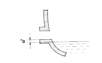 |
Add manual transmission oil until the oil level is within 5 mm (0.197 in.) from the bottom of the manual transmission filler plug opening.
| *a | 0 to 5 mm (0 to 0.197 in.) |
Check for oil leakage when the oil level is low.
Install the transmission filler plug and a new gasket.
| 27. INSPECT FOR MANUAL TRANSMISSION OIL LEAK |