 |
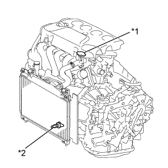
Loosen the radiator drain cock plug.
| *1 | Water Filler Cap Sub-assembly |
| *2 | Radiator Drain Cock Plug |
ENGINE ASSEMBLY (for Hatchback) > REMOVAL |
| 1. REMOVE ENGINE UNDER COVER LH |
| 2. REMOVE ENGINE UNDER COVER RH |
| 3. REMOVE FRONT WHEELS |
| 4. DISCHARGE FUEL SYSTEM PRESSURE |
| 5. DRAIN ENGINE COOLANT |
|
Loosen the radiator drain cock plug.
| *1 | Water Filler Cap Sub-assembly |
| *2 | Radiator Drain Cock Plug |
Remove the water filler cap sub-assembly, then drain coolant.
| 6. DRAIN AUTOMATIC TRANSAXLE FLUID (for Automatic Transaxle) |
Remove the drain plug and gasket, and drain ATF.
Install a new gasket and the drain plug.
| 7. DRAIN MANUAL TRANSAXLE OIL (for Manual Transaxle) |
Remove the filler plug and the gasket.
Remove the drain plug and gasket, and then drain the manual transaxle oil.
| 8. REMOVE WINDSHIELD WIPER MOTOR AND LINK ASSEMBLY |
| 9. REMOVE FRONT NO. 1 VENTILATOR SEAL |
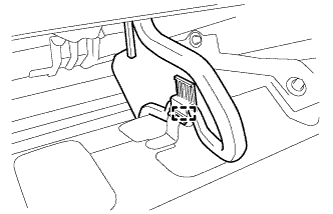 |
Disengage the clamp and remove the front No. 1 ventilator seal.
| 10. REMOVE FRONT AIR SHUTTER SEAL RH |
| 11. REMOVE INNER COWL TOP TO COWL BRACE |
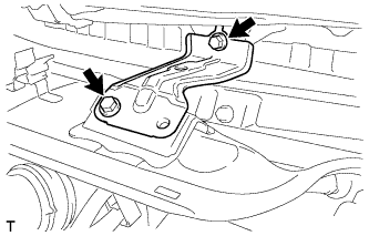 |
Remove the 2 bolts and the inner cowl top to cowl brace.
| 12. REMOVE OUTER COWL TOP PANEL |
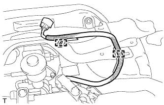 |
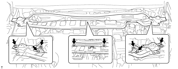
Disengage the 2 clamps and separate the wire harness.
Remove the 8 bolts and the outer cowl top panel.
| 13. REMOVE BATTERY |
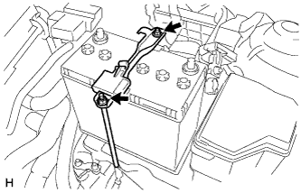 |
Disconnect the cable from the battery terminal.
Loosen the 2 nuts and remove the battery clamp.
Remove the battery.
| 14. REMOVE BATTERY TRAY |
| 15. REMOVE NO. 2 CYLINDER HEAD COVER |
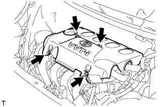 |
Remove the 4 nuts and No. 2 cylinder head cover.
| 16. REMOVE AIR CLEANER ASSEMBLY |
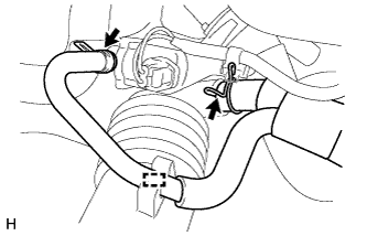 |
Disengage the clamp and disconnect the fuel vapor feed hose assembly from the No. 1 air cleaner hose.
Loosen the 2 hose clamps and disconnect the fuel vapor feed hose assembly from the No. 1 air cleaner hose and vacuum switching valve assembly.
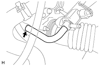 |
Disconnect the No. 2 fuel vapor feed hose from the intake manifold.
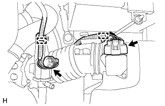 |
Disengage the 2 clamps and disconnect the wire harness from the air cleaner cap sub-assembly and vacuum switching valve assembly.
Disconnect the mass air flow meter connector.
Disconnect the vacuum switching valve connector.
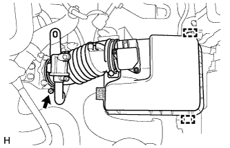 |
Loosen the hose clamp and disconnect the No. 1 air cleaner hose from the throttle with motor body assembly.
Disengage the 2 clamps and remove the air cleaner cap sub-assembly with No. 1 air cleaner hose.
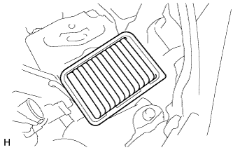 |
Remove the air cleaner element.
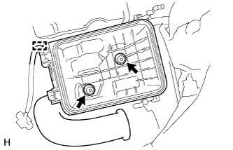 |
Disengage the clamp and disconnect the wire harness from the air cleaner case.
Remove the 2 bolts and the air cleaner case from the air cleaner bracket.
| 17. REMOVE AIR CLEANER BRACKET |
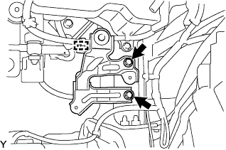 |
Disengage the clamp and disconnect the wire harness from the air cleaner bracket.
Remove the 2 bolts and the air cleaner bracket.
| 18. REMOVE BATTERY CARRIER |
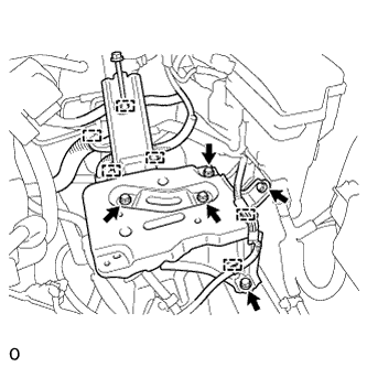 |
Disengage the 6 clamps and disconnect the wire harness from the battery carrier.
Remove the 5 bolts and the battery carrier.
| 19. REMOVE FUEL VAPOR FEED HOSE ASSEMBLY |
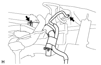 |
Loosen the 2 hose clamps and remove the fuel vapor feed hose assembly.
| 20. DISCONNECT RADIATOR RESERVOIR TANK HOSE |
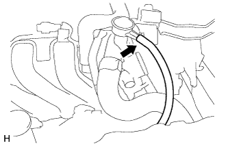 |
Disconnect the radiator reservoir tank hose from the water filler.
| 21. DISCONNECT NO. 3 RADIATOR HOSE |
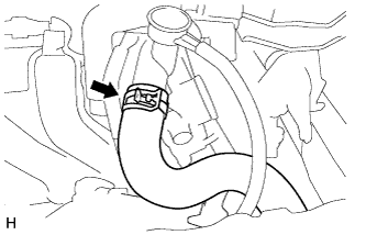 |
Loosen the hose clamp and disconnect No. 3 radiator hose from the water filler.
| 22. DISCONNECT NO. 2 RADIATOR HOSE |
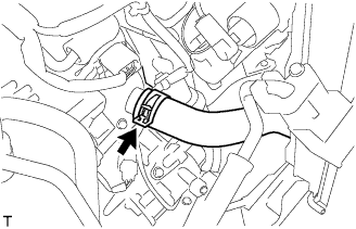 |
Loosen the hose clamp and disconnect No. 2 radiator hose from the water inlet.
| 23. REMOVE EFI FUEL PIPE CLAMP |
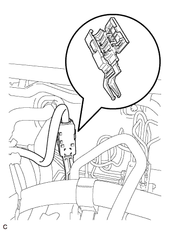 |
Remove the fuel pipe clamp.
| 24. DISCONNECT FUEL TUBE SUB-ASSEMBLY |
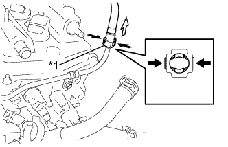 |
Pinch the retainer as illustrated, then pull the fuel tube connector out of the pipe.
| *1 | Retainer |
 | Pinch |
 | Pull |
| 25. DISCONNECT OUTLET OIL COOLER HOSE (for Automatic Transaxle) |
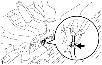 |
Loosen the hose clamp and disconnect the oil cooler outlet hose.
| 26. DISCONNECT INLET OIL COOLER HOSE (for Automatic Transaxle) |
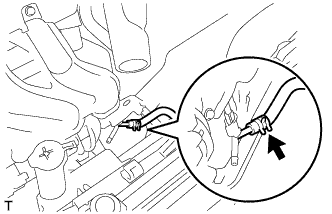 |
Loosen the hose clamp and disconnect the oil cooler inlet hose.
| 27. DISCONNECT UNION TO CHECK VALVE HOSE |
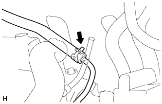 |
Loosen the hose clamp and disconnect the union to check valve hose from the booster vacuum tube.
| 28. DISCONNECT OUTLET HEATER WATER HOSE A |
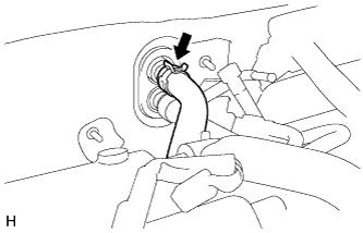 |
Loosen the hose clamp and disconnect outlet heater water hose A from the heater unit.
| 29. DISCONNECT INLET HEATER WATER HOSE A |
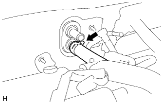 |
Loosen the hose clamp and disconnect inlet heater water hose A from the heater unit.
| 30. REMOVE FAN AND GENERATOR V BELT |
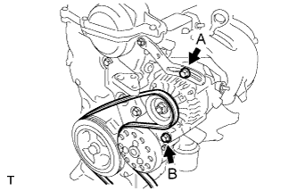 |
Loosen bolts A and B.
Release the fan and generator V belt tension and remove the fan and generator V belt.
| 31. SEPARATE CLUTCH RELEASE CYLINDER ASSEMBLY (for Manual Transaxle) |
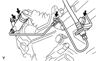 |
Remove the 4 bolts, then separate the clutch release cylinder assembly.
| 32. SEPARATE COMPRESSOR WITH PULLEY ASSEMBLY (w/ Air Conditioning System) |
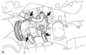 |
Disconnect the connector.
Remove the 4 bolts and separate the compressor with pulley assembly.
| 33. DISCONNECT ENGINE WIRE |
for Automatic Transaxle:
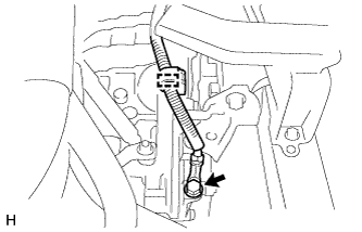 |
Disengage the clamp and disconnect the wire harness from the automatic transaxle.
Remove the bolt and separate the wire harness from the automatic transaxle.
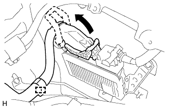 |
Disengage the wire harness clamp and separate the wire harness.
Pull up the lever and disconnect the connector of the engine control computer.
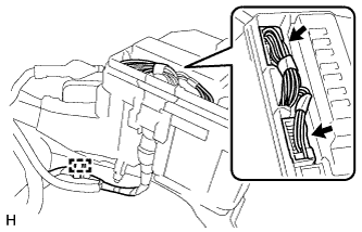 |
Disengage the clamp and disconnect the wire harness.
Disconnect the 2 connectors.
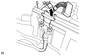 |
Disengage the 2 claws and disconnect the wire harness from the engine room relay block.
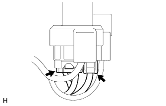 |
Disconnect the 2 connectors from the battery positive terminal.
Disconnect all the wire harnesses and connectors. Make sure that no wire harness is connected between the body and engine.
| 34. SEPARATE TRANSMISSION CONTROL CABLE ASSEMBLY (for Automatic Transaxle) |
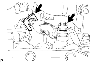 |
Remove the nut and disconnect the transmission control cable assembly from the control shaft lever.
Remove the clip and separate the transmission control cable assembly from the No. 1 transmission control cable bracket.
| 35. SEPARATE TRANSMISSION CONTROL CABLE ASSEMBLY (for Manual Transaxle) |
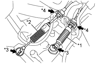 |
Remove the clip A and washer, and separate the control shift cable from the manual transaxle assembly.
| *1 | Control Shift Cable |
| *2 | Control Select Cable |
| *3 | Clip A |
| *4 | Clip B |
Remove the clip B from the control shift cable, and separate the control shift cable from the shift cable bracket.
Remove the clip A and washer, and separate the control select cable from the manual transaxle assembly.
Remove the clip B from the control select cable, and separate the control select cable from the shift cable bracket.
| 36. REMOVE REAR CONSOLE BOX ASSEMBLY |
| 37. REMOVE FRONT FLOOR CENTER BRACE |
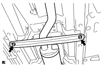 |
Remove the 2 bolts and the front floor center brace from the body.
| 38. REMOVE FRONT EXHAUST PIPE ASSEMBLY |
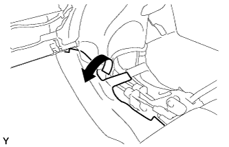 |
Peel back the floor carpet.
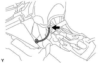 |
Disconnect the heated oxygen sensor connector.
Remove the oxygen sensor wire grommet and pass the connector through the hole to the outside of the vehicle.
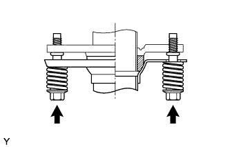 |
Remove the 2 bolts and 2 compression springs from the exhaust manifold.
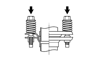 |
Remove the 2 bolts and 2 compression springs from the tail exhaust pipe assembly.
Remove the 3 exhaust pipe supports and the front exhaust pipe assembly.
| 39. REMOVE EXHAUST PIPE GASKET |
Remove the exhaust pipe gasket from the exhaust manifold.
| 40. REMOVE NO. 2 EXHAUST PIPE GASKET |
Remove the No. 2 exhaust pipe gasket from the front exhaust pipe assembly.
| 41. REMOVE FRONT DRIVE SHAFT ASSEMBLY LH |
| 42. REMOVE FLYWHEEL HOUSING UNDER COVER (for Automatic Transaxle) |
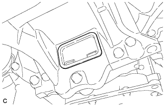 |
Remove the flywheel housing under cover.
| 43. REMOVE TORQUE CONVERTER SETTING BOLT (for Automatic Transaxle) |
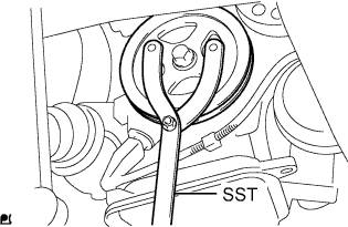 |
Hold the crankshaft with SST.
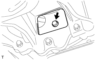 |
Remove the 6 torque converter set bolts.
| 44. REMOVE COLUMN HOLE COVER SILENCER SHEET |
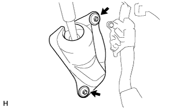 |
Remove the 2 clips and the column hole cover silencer sheet.
| 45. SEPARATE STEERING SLIDING YOKE SUB-ASSEMBLY |
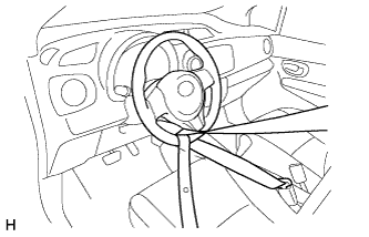 |
Use a seat belt to fix the steering wheel assembly, in order to avoid breakage of the spiral cable.
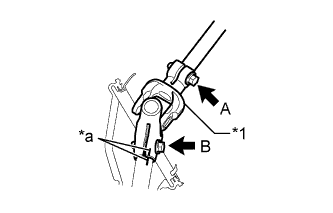 |
Place matchmarks on the steering sliding yoke sub-assembly and the steering gear assembly.
| *1 | Steering Sliding Yoke Sub-assembly |
| *a | Matchmark |
Loosen bolt A, remove bolt B and separate the steering sliding yoke sub-assembly from the steering gear assembly.
| 46. REMOVE NO. 1 STEERING COLUMN HOLE COVER SUB-ASSEMBLY |
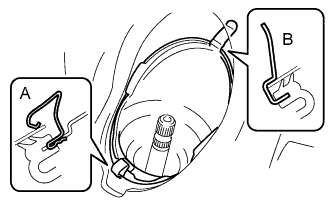 |
Remove clip A, separate clip B from the body and separate the No. 1 steering column hole cover sub-assembly.
| 47. REMOVE ENGINE ASSEMBLY WITH TRANSAXLE |
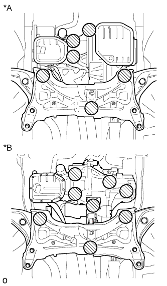 |
Place the wooden blocks or plate lift attachments in the positions shown in the illustration and set an engine lifter underneath the engine assembly with transaxle.
| *A | for Automatic Transaxle |
| *B | for Manual Transaxle |
 | Attachment Placement Position |
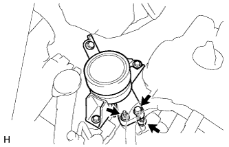 |
Remove the bolt, 2 nuts and the engine mounting insulator RH.
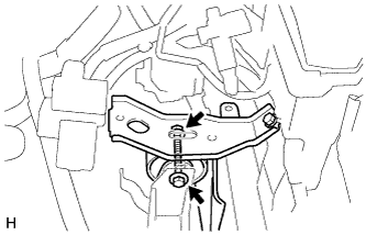 |
Remove the through bolt and the nut and separate the engine mounting insulator LH.
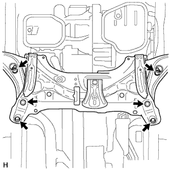 |
Remove the 6 bolts, and remove the engine assembly with transaxle and the front suspension crossmember from the vehicle.
| 48. INSTALL NO. 1 ENGINE HANGER |
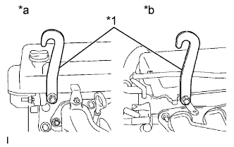 |
Remove the bolt and the wire harness bracket.
Install the 2 engine hangers with the 2 bolts, as shown in the illustration.
| *1 | No. 1 Engine Hanger |
| *a | Front Side |
| *b | Rear Side |
| Part Name | Part No. |
| Engine hanger | 12281-21010 |
| Bolt | 91642-81025 |
| 49. REMOVE FRONT SUSPENSION CROSSMEMBER SUB-ASSEMBLY |
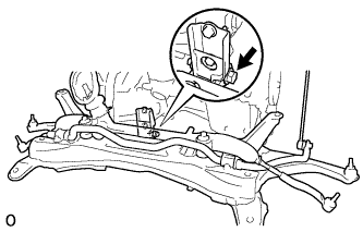 |
Using an engine sling device and a chain block, suspend the engine assembly with transaxle and front suspension crossmember.
Remove the through bolt from the engine moving control rod and remove the front suspension crossmember.
| 50. REMOVE NO. 1 IGNITION COIL |
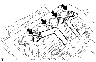 |
Disconnect the 4 No. 1 ignition coil connectors.
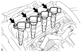 |
Remove the 4 bolts and the 4 No. 1 ignition coils.
| 51. REMOVE ENGINE WIRE |
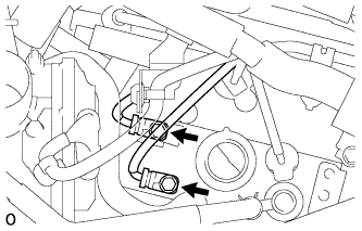 |
Remove the 2 ground bolts.
Disconnect all the wire harnesses and connectors. Make sure that no wire harnesses are connected to the engine.
| 52. REMOVE VENTILATION HOSE |
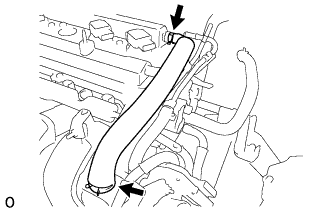 |
Loosen the 2 hose clamps and remove the ventilation hose.
| 53. REMOVE WATER FILLER SUB-ASSEMBLY |
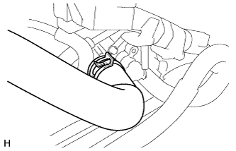 |
Loosen the hose clamp and disconnect radiator hose No. 1 from the cylinder head.
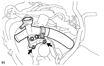 |
Remove the 2 nuts and the water filler sub-assembly.
| 54. REMOVE INTAKE MANIFOLD |
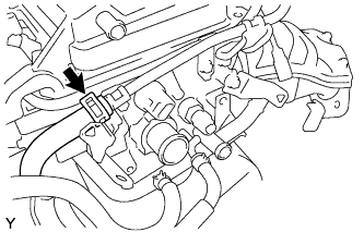 |
Loosen the hose clamp and disconnect the union to connector tube hose from the booster vacuum tube.
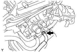 |
Loosen the hose clamp and disconnect the water by-pass hose from the cylinder head.
Disconnect the water by-pass hose from the No. 1 water by-pass pipe.
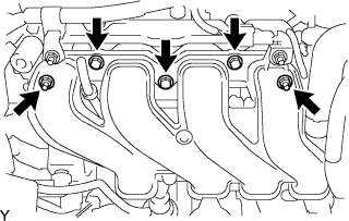 |
Remove the 3 bolts, 2 nuts and the intake manifold.
Remove the gasket from the intake manifold.
| 55. REMOVE NO. 1 EXHAUST MANIFOLD HEAT INSULATOR |
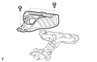 |
Remove the 4 bolts and the No. 1 exhaust manifold heat insulator.
| 56. REMOVE MANIFOLD SUPPORT BRACKET |
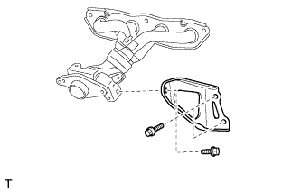 |
Remove the 3 bolts and the manifold support bracket.
| 57. REMOVE EXHAUST MANIFOLD |
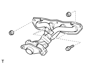 |
Remove the 3 bolts, 2 nuts and the exhaust manifold.
| 58. FIX ENGINE ASSEMBLY |
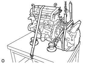 |
Using an engine sling device and a chain block, hold the engine assembly.
To enable removal of the engine assembly, adjust the positions of the plate lift attachments and set them in place.
Use a belt with a tightening mechanism or a rope to secure the engine assembly with transaxle to the engine lifter.
| 59. REMOVE FLYWHEEL HOUSING SIDE COVER |
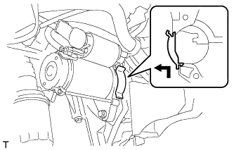 |
Disengage the claw by pulling it outward and remove the flywheel housing side cover.
| 60. REMOVE STARTER ASSEMBLY |
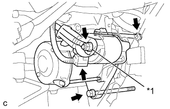 |
Remove the terminal cap.
Remove the nut and disconnect terminal 30.
Disconnect the connector.
Remove the 2 bolts and starter assembly.
| *1 | Terminal 30 |
| 61. REMOVE AUTOMATIC TRANSAXLE ASSEMBLY (for Automatic Transaxle) |
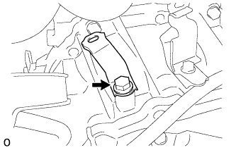 |
Remove the bolt and wire harness bracket from the automatic transaxle assembly.
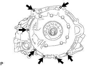 |
Remove the 7 bolts and the automatic transaxle assembly with torque converter.
| 62. REMOVE CONTROL CABLE BRACKET (for Manual Transaxle) |
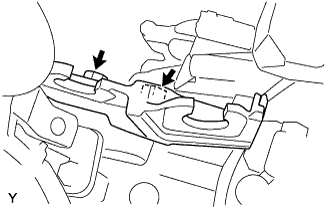 |
Remove the 2 bolts and the control cable bracket.
| 63. REMOVE DRIVE PLATE AND RING GEAR SUB-ASSEMBLY (for Automatic Transaxle) |
|
Hold the crankshaft with SST.
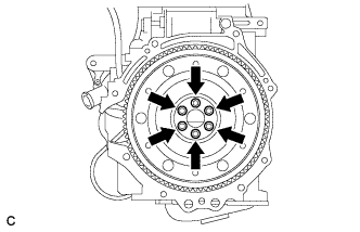 |
Remove the 6 bolts, drive plate spacer FR, drive plate and ring gear sub-assembly and drive plate spacer RR.
| 64. REMOVE MANUAL TRANSAXLE ASSEMBLY (for Manual Transaxle) |
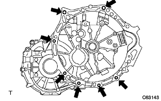 |
Remove the 7 bolts and the manual transaxle assembly.
| 65. REMOVE CLUTCH COVER ASSEMBLY (for Manual Transaxle) |
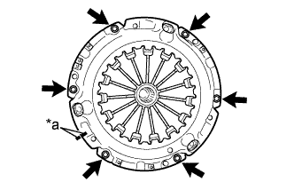 |
Put the matchmarks on the clutch cover assembly and the flywheel sub-assembly.
| *a | Matchmark |
Loosen the 6 bolts one turn at a time until spring tension is released.
Remove the 6 bolts and pull off the clutch cover assembly.
| 66. REMOVE CLUTCH DISC ASSEMBLY (for Manual Transaxle) |
Remove the clutch disc assembly.
| 67. REMOVE FLYWHEEL SUB-ASSEMBLY (for Manual Transaxle) |
|
Hold the crankshaft with SST.
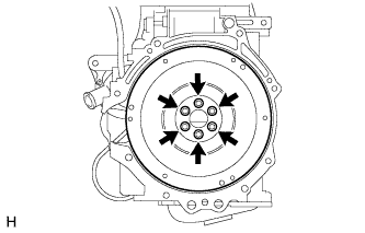 |
Remove the 6 bolts and flywheel.
| 68. REMOVE INLET HEATER WATER HOSE A |
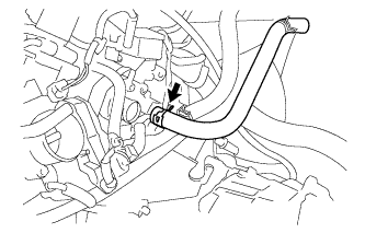 |
Disconnect heater water inlet hose A from the cylinder head.
| 69. REMOVE DRIVE SHAFT HEAT INSULATOR SUB-ASSEMBLY |
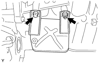 |
Remove the bolt, nut and the drive shaft heat insulator.
| 70. REMOVE ENGINE MOUNTING INSULATOR RH |
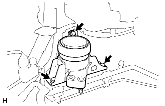 |
Remove the 3 bolts and engine mounting insulator RH.
| 71. REMOVE ENGINE MOUNTING INSULATOR LH |
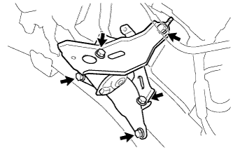 |
Remove the 5 bolts and engine mounting insulator LH.