Home › Drivetrain ยท AXLE AND DIFFERENTIAL › FRONT AXLE HUB (for Sedan)

FRONT AXLE HUB (for Sedan) > INSTALLATION

for Preparation Click here


1. INSTALL FRONT AXLE HUB BEARING


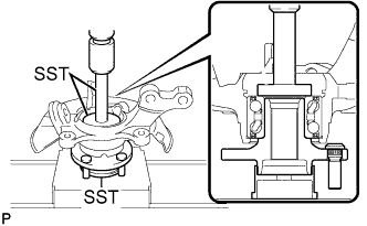
G031910E01
  1. Using SST and a press, insert a new hub bearing, with its magnetic rotor side facing the inside of the vehicle, until it reaches the end of the steering knuckle.

    SST
    09950-60020   (09951-00710)
    09950-70010   (09951-07100)

    NOTICE:
    1. Do not remove the hub bearing inner race because the hub bearing is built into the oil seal.
    2. Do not use hub bearings that have been removed.
    3. Do not wipe off any grease that has been applied to new hub bearings.
    4. Do not bring magnets close to the magnetic rotor surface of the hub bearing.
    5. Keep the magnetic rotor surface of the hub bearing free of foreign matter.


2. INSTALL FRONT DISC BRAKE DUST COVER


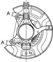
    C112273E04
  1. Temporarily install a new disc brake dust cover, as shown in the illustration.
    Standard clearance A:
    19.8 mm (0.78 in.)


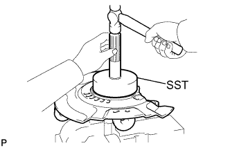
    C116903E01
  1. Using SST and a hammer, install the disc brake dust cover.
    SST
    09223-56010  

    NOTICE:
    1. Uniformly press in the disc brake dust cover while sliding SST slightly.
    2. Surely press in the disc brake dust cover until the pressing-in base.


    C278281
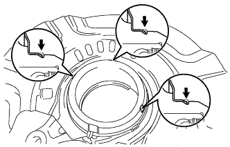
  1. Using a chisel, fix the 3 points on the circumference.

    NOTICE:
    Securely fold each end into the engagement grooves.


3. INSTALL FRONT AXLE HUB SUB-ASSEMBLY


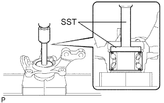
C107983E01
  1. Using SST and a press, press the axle hub into the steering knuckle.

    SST
    09608-32010  
    09950-60010   (09951-00500)
    09950-70010   (09951-07100)


4. INSTALL FRONT AXLE HUB HOLE SNAP RING


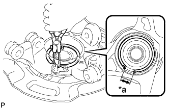
    C112581E03
  1. Using snap ring pliers, install a new hole snap ring, as shown in the illustration.
    Text in Illustration 
    *a
    Hole

    NOTICE:
    1. Do not overlap the end of the hole snap ring and the installation hole in the speed sensor on the knuckle side.
    2. Do not damage the magnetic rotor surface of the hub bearing when installing the hole snap ring.


5. INSTALL FRONT AXLE ASSEMBLY
  1. Install the front axle assembly to the shock absorber.

  1. Install the 2 bolts and 2 nuts.

    Torque:
    164 N*m{ 1672 kgf*cm , 121 ft.*lbf }

    HINT:
    Keep the nut from rotating while turning the bolt.

  1. Push the front axle out of the vehicle to align the spline of the drive shaft with the front axle and insert the front axle.

    NOTICE:
    1. Do not push the front axle further out of the vehicle than is necessary.
    2. Do not damage the outboard joint boot.
    3. Check for any foreign matter on the speed sensor rotor and insertion part.
    4. Do not damage the speed sensor rotor.


6. INSTALL FRONT LOWER SUSPENSION ARM
  1. Install the lower arm to the steering knuckle with a new castle nut.

    Torque:
    98 N*m{ 1000 kgf*cm , 72 ft.*lbf }

    NOTICE:
    If the holes for the clip are not aligned, tighten the nut by a further turn of up to 60°.

  1. Install a new clip.


7. INSTALL TIE ROD END SUB-ASSEMBLY
  1. Install the tie rod end to the steering knuckle with a new castle nut.

    Torque:
    49 N*m{ 500 kgf*cm , 36 ft.*lbf }

    NOTICE:
    If the holes for the clip are not aligned, tighten the nut by a further turn of up to 60°.

  1. Install a new cotter pin.


8. INSTALL FRONT STABILIZER LINK ASSEMBLY
  1. Install the stabilizer link to the shock absorber with the nut.

    Torque:
    74 N*m{ 755 kgf*cm , 55 ft.*lbf }

    HINT:
    If the ball joint turns together with the nut, use a socket hexagon wrench 6 to hold the stud.


9. INSTALL FRONT DISC


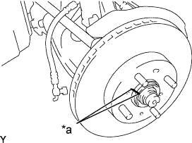
C108932E02
  1. Align the matchmarks of the disc and axle hub and install the disc.
    Text in Illustration 
    *a
    Matchmark

    NOTICE:
    When replacing the disc, select the position that gives the minimum disc runout.


10. INSTALL FRONT DISC BRAKE CALIPER ASSEMBLY
  1. Install the disc brake caliper onto the steering knuckle.

    Torque:
    107 N*m{ 1089 kgf*cm , 79 ft.*lbf }


11. INSTALL FRONT SPEED SENSOR (w/ ABS)
  1. Install the speed sensor to the steering knuckle with the bolt.

    Torque:
    8.5 N*m{ 87 kgf*cm , 75 in.*lbf }

    NOTICE:
    1. Check that the speed sensor tip and installation portion are free of foreign matter.
    2. Install the speed sensor without turning it from its original installation angle.

  1. Install the flexible hose and the speed sensor with the bolt.

    Torque:
    29 N*m{ 300 kgf*cm , 22 ft.*lbf }

    NOTICE:
    Install the flexible hose and speed sensor without twisting them.


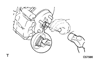
12. INSTALL FRONT AXLE HUB NUT


C057566
  1. Using a 30 mm socket wrench, install a new axle hub nut.

    Torque:
    216 N*m{ 2,203 kgf*cm , 160 ft.*lbf }

  1. Using a chisel and a hammer, stake the axle hub nut.


13. INSPECT FRONT AXLE HUB BEARING


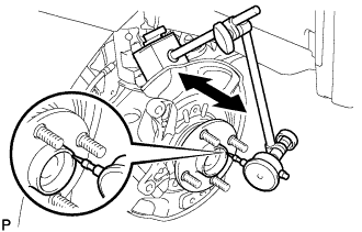
C107912
  1. Inspect the axle hub backlash.

    1. Using a dial indicator, check the backlash near the center of the axle hub.
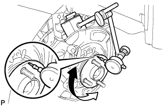
      Maximum:
      0.05 mm (0.0020 in.)

      If the backlash exceeds the maximum, replace the bearing.


    C107911
  1. Inspect the axle hub runout.

    1. Using a dial indicator, check the runout of the surface of the axle hub.

      Maximum:
      0.05 mm (0.0020 in.)

      If the runout exceeds the maximum, replace the bearing and axle hub.


14. INSTALL FRONT WHEEL

Torque:
103 N*m{ 1050 kgf*cm , 76 ft.*lbf }


15. INSPECT AND ADJUST FRONT WHEEL ALIGNMENT
(Click here)


16. CONNECT CABLE TO NEGATIVE BATTERY TERMINAL

Torque:
5.4 N*m{ 55 kgf*cm , 48 in.*lbf }


17. CHECK ABS SENSOR SIGNAL (w/ ABS)
(Click here)