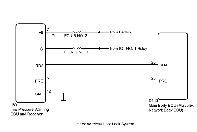
DTC B1247 Tire Pressure Monitor Receiver Communication Stop |
| DTC No. | DTC Detection Condition | Trouble Area |
| B1247 | In diagnostic mode, an applicable RDA signal cannot be received within 2.4 seconds after a PRG signal has been output from the main body ECU (multiplex network body ECU). |
|
| 1.CHECK HARNESS AND CONNECTOR (MAIN BODY ECU (MULTIPLEX NETWORK BODY ECU) - TIRE PRESSURE) |
Disconnect the tire pressure warning ECU and receiver J69 connector.
Measure the resistance according to the value(s) in the table below.
| Tester Connection | Condition | Specified Condition |
| J69-4 (RDA) - D143-26 (RDA) | Always | Below 1 Ω |
| D143-26 (RDA) - Body ground | Always | 10 kΩ or higher |
|
| ||||
| OK | |
 |
| 2.CHECK HARNESS AND CONNECTOR (POWER SOURCE OF TIRE PRESSURE WARNING ECU AND RECEIVER) |
Measure the resistance according to the value(s) in the table below.
| Tester Connection | Condition | Specified Condition |
| J69-12 (GND) - Body ground | Always | Below 1 Ω |
Measure the voltage according to the value(s) in the table below.
| Tester Connection | Switch Condition | Specified Condition |
| J69-1 (IG) - Body ground | Ignition switch ON | 11 to 14 V |
|
| ||||
| OK | |
|
| 3.REPLACE TIRE PRESSURE WARNING ECU AND RECEIVER |
Replace the tire pressure warning ECU and receiver (Click here).
| NEXT | |
|
| 4.CHECK DTC OUTPUT (B1247) |
Clear the DTCs (Click here).
Turn the ignition switch off.
Turn the ignition switch to ON.
Check for DTCs (Click here).
|
| ||||
| OK | ||
 | ||
| ||
