 |
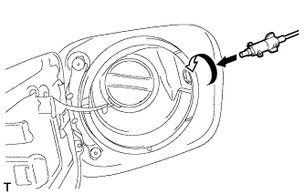
Install the fuel lid lock control cable sub-assembly by inserting it and turning it clockwise, as shown in the illustration.
FUEL LID LOCK CONTROL CABLE ASSEMBLY (for Sedan) > INSTALLATION |
| 1. INSTALL FUEL LID LOCK CONTROL CABLE SUB-ASSEMBLY |
|
Install the fuel lid lock control cable sub-assembly by inserting it and turning it clockwise, as shown in the illustration.
Engage the fuel lid lock control cable sub-assembly to the 5 clamps as shown in the illustration.
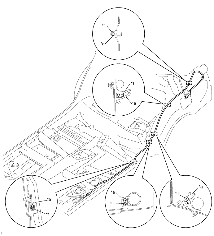
| *1 | Fuel Lid Lock Control Cable Sub-assembly | - | - |
| *a | Clamp | - | - |
| 2. INSTALL FUEL LID LOCK OPEN LEVER SUB-ASSEMBLY |
Engage the 2 guides and connect the fuel lid lock control cable sub-assembly and luggage door lock control cable sub-assembly to the fuel lid lock open lever sub-assembly.
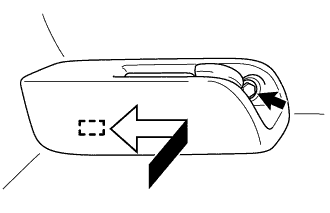 |
Engage the guide and install the fuel lid lock open lever sub-assembly in the direction indicated by the arrow as shown in the illustration.
Install the screw.
| 3. INSTALL REAR SEAT SIDE COVER LH |
| 4. INSTALL CENTER PILLAR LOWER GARNISH LH |
| 5. INSTALL FRONT SEAT OUTER BELT ASSEMBLY LH |
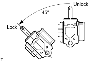 |
Check the angle of inclination required to lock the retractor.
Gently incline the retractor from its initial position. Check that the belt does not lock when the retractor is inclined 15 ° or less in any direction. Also, check that the belt locks when the inclination of the retractor is 45 ° or more.
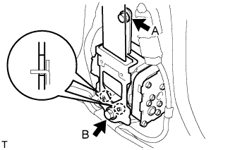 |
Hook the lower stay of the retractor onto the 2 body hooks and provisionally install the retractor with the 2 bolts.
Tighten bolt A and then bolt B.
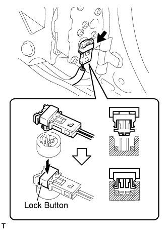 |
Connect the pretensioner connector.
Connect the pretensioner connector.
Lock the locking button.
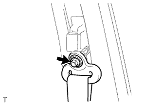 |
Install the shoulder anchor with the bolt.
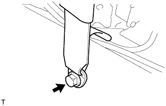 |
Install the anchor plate with the bolt.
Check that the ELR locks.
With the belt installed, check that the belt locks when it is pulled out quickly.
If the operation is not as specified, replace the front seat outer belt.
| 6. INSTALL LAP BELT OUTER ANCHOR COVER |
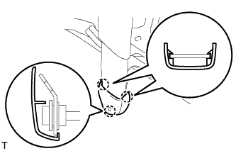 |
Engage the 3 claws and install the lap belt outer anchor cover.
| 7. INSTALL REAR DOOR OPENING TRIM WEATHERSTRIP LH |
| 8. INSTALL REAR DOOR SCUFF PLATE LH |
| 9. INSTALL FRONT DOOR OPENING TRIM WEATHERSTRIP LH |
| 10. INSTALL COWL SIDE TRIM BOARD LH |
| 11. INSTALL FRONT DOOR SCUFF PLATE LH |
| 12. INSTALL LUGGAGE COMPARTMENT TRIM INNER COVER LH |
| 13. INSTALL REAR FLOOR FINISH PLATE |
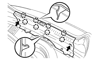 |
Engage the 8 claws and install the rear floor finish plate.
Install the 2 clips.
| 14. INSTALL DECK FLOOR BOX LH |
| 15. INSTALL LUGGAGE COMPARTMENT TRIM INNER PAD |
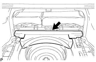 |
Install the luggage compartment trim inner pad.
| 16. INSTALL SPARE WHEEL COVER ASSEMBLY |
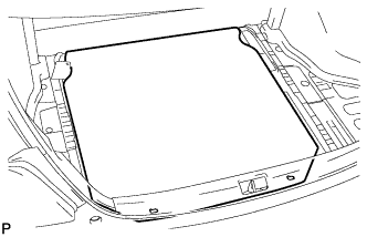 |
Install the spare wheel cover assembly.
| 17. INSTALL REAR SEAT ASSEMBLY LH |
| 18. INSTALL FRONT SEAT ASSEMBLY |