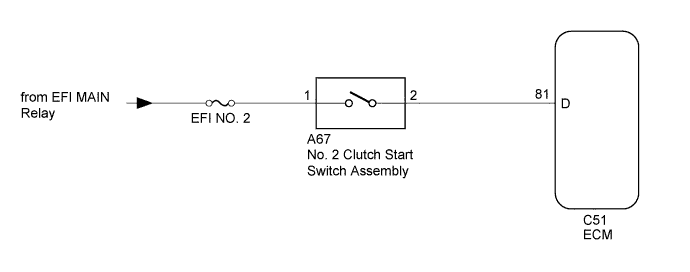
CRUISE CONTROL SYSTEM (for Hatchback) > Clutch Switch Circuit |
| 1.INSPECT NO. 2 CLUTCH START SWITCH ASSEMBLY |
Inspect the No. 2 clutch start switch assembly (Click here).
|
| ||||
| OK | |
 |
| 2.CHECK HARNESS AND CONNECTOR (NO. 2 CLUTCH START SWITCH ASSEMBLY - ECM AND BATTERY) |
Disconnect the A67 No. 2 clutch start switch assembly connector.
Disconnect the C51 ECM connector.
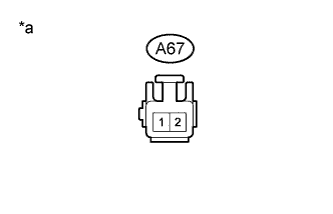 |
Measure the voltage according to the value(s) in the table below.
| Tester Connection | Switch Condition | Specified Condition |
| A67-1 - Body ground | Ignition switch ON | 11 to 14 V |
| Ignition switch off | Below 1 V |
| *a | Front view of wire harness connector (to No. 2 Clutch Start Switch Assembly) |
Measure the resistance according to the value(s) in the table below.
| Tester Connection | Condition | Specified Condition |
| A67-2 - C51-81 (D) | Always | Below 1 Ω |
| A67-2 - Body ground | Always | 10 kΩ or higher |
|
| ||||
| OK | ||
 | ||
| ||
