1NZ-FE FUEL FUEL INJECTOR INSTALLATION
PROCEDURE

 23250
1.INSTALL FUEL INJECTOR ASSEMBLY
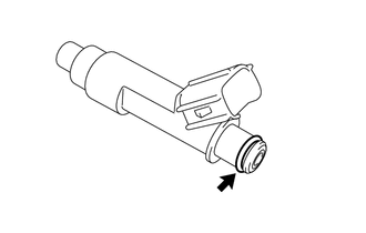
Apply a light coat of gasoline or spindle oil to new O-rings, and then install one to each fuel injector assembly.
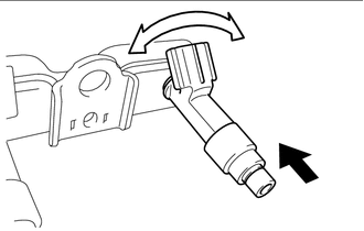

|
Push |

|
Turn |
Apply a light coat of gasoline or spindle oil to the contact surfaces of the O-ring on each fuel injector assembly.
While turning the fuel injector assembly left and right, install it to the fuel delivery pipe sub-assembly.
- NOTICE:
- ·
Make sure that the O-ring is not cracked or pinched when installing the fuel injector assembly.
·If a part has been dropped or subjected to a strong impact, replace it.
23291
2.INSTALL INJECTOR VIBRATION INSULATOR
Install 4 new injector vibration insulators to the cylinder head sub-assembly.
23891
3.INSTALL FUEL DELIVERY SPACER
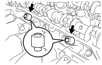
| *a | Fuel Delivery Pipe Sub-assembly Side |
| *b | Cylinder Head Sub-assembly Side |
Install the 2 fuel delivery spacers to the cylinder head sub-assembly.
- NOTICE:
-
Install the fuel delivery spacer in the correct direction.
23807
4.INSTALL FUEL DELIVERY PIPE SUB-ASSEMBLY
Temporarily install the fuel delivery pipe sub-assembly together with 4 fuel injector assemblies to the cylinder head sub-assembly with the 3 bolts.
- NOTICE:
- ·
Do not drop the fuel injector assemblies when installing the fuel delivery pipe sub-assembly.
·Check that the fuel injector assemblies rotate smoothly after installing the fuel delivery pipe sub-assembly.
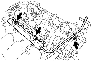
Tighten the 2 bolts A.
- Torque:
- 19 N*m (194 kgf*cm, 14 ft.*lbf)
Tighten the bolt B.
- Torque:
- 9.0 N*m (92 kgf*cm, 80 in.*lbf)
23901
5.CONNECT FUEL TUBE SUB-ASSEMBLY
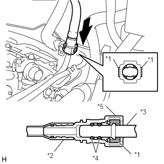
| *1 | Retainer |
| *2 | Nylon Tube |
| *3 | Fuel Delivery Pipe Sub-assembly |
| *4 | O-ring |
| *5 | Fuel Tube Connector |
|
|
Push |
Push the fuel tube connector to the fuel pipe until the fuel delivery pipe sub-assembly connector makes a "click" sound.
- NOTICE:
- ·
Before connecting the fuel tube connector and fuel delivery pipe sub-assembly, check that there is no damage or foreign matter on the connecting part of the fuel delivery pipe sub-assembly.
·After connecting the fuel tube connector and fuel delivery pipe sub-assembly, check that they are securely connected by trying to pull them apart.
23842A
6.INSTALL EFI FUEL PIPE CLAMP
Install the EFI fuel pipe clamp to the fuel tube sub-assembly and fuel delivery pipe sub-assembly.
Close the cover of the EFI fuel pipe clamp to engage the claw.
11201
7.INSTALL CYLINDER HEAD COVER SUB-ASSEMBLY
Install a new cylinder head cover gasket to the cylinder head cover sub-assembly.
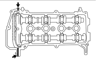
|
|
Apply Seal Packing |
Apply seal packing to the 2 locations shown in the illustration.
- Seal packing:
Toyota Genuine Seal Packing Black, Three Bond 1207B or equivalent
- NOTICE:
- ·
Remove any oil from the contact surfaces.
·Install the cylinder head cover sub-assembly within 3 minutes and tighten the bolts within 15 minutes after applying seal packing.
·Do not start the engine for at least 2 hours after the installation.
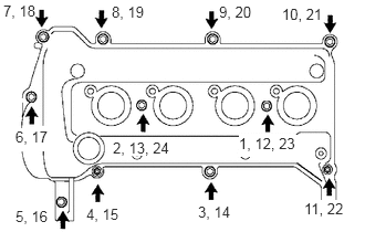
Temporarily install the cylinder head cover sub-assembly to the cylinder head sub-assembly with the 9 bolts, 2 nuts and 2 new cylinder head cover seal washers.
Using several steps, tighten the 9 bolts and 2 nuts in the sequence shown in the illustration.
- Torque:
- 10 N*m (102 kgf*cm, 7 ft.*lbf)
Engage the 2 clamps to connect the wire harness to the 2 wire harness clamp brackets.
Connect the 4 fuel injector assembly connectors.
23820
8.CONNECT FUEL VAPOR FEED HOSE ASSEMBLY
Connect the fuel vapor feed hose assembly to the cylinder head cover sub-assembly with the hose clip.
12261
9.CONNECT VENTILATION HOSE
19500D
10.INSTALL NO. 1 IGNITION COIL
11.INSPECT FOR FUEL LEAK
12.INSPECT FOR ENGINE OIL LEAK
11212
13.INSTALL NO. 2 CYLINDER HEAD COVER