1NZ-FE FUEL FUEL INJECTOR REMOVAL
PROCEDURE

 1. DISCHARGE FUEL SYSTEM PRESSURE
11212
2.REMOVE NO. 2 CYLINDER HEAD COVER
19500D
3.REMOVE NO. 1 IGNITION COIL
12261
4.DISCONNECT VENTILATION HOSE
23820
5.DISCONNECT FUEL VAPOR FEED HOSE ASSEMBLY
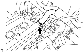
Loosen the hose clip and disconnect the fuel vapor feed hose assembly from the cylinder head cover sub-assembly.
11201
6.REMOVE CYLINDER HEAD COVER SUB-ASSEMBLY
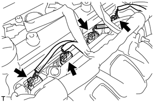
Disconnect the 4 fuel injector assembly connectors.
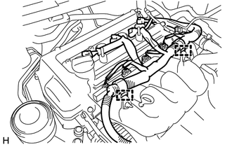
Disengage the 2 clamps to disconnect the wire harness from the 2 wire harness clamp brackets.
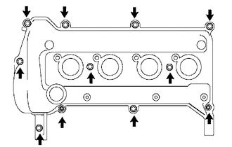
Remove the 9 bolts, 2 nuts, 2 cylinder head cover seal washers and cylinder head cover sub-assembly from the cylinder head sub-assembly.
Remove the cylinder head cover gasket from the cylinder head cover sub-assembly.
23842A
7.REMOVE EFI FUEL PIPE CLAMP
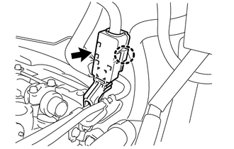
Disengage the claw to open the cover of the EFI fuel pipe clamp.
Remove the EFI fuel pipe clamp from the fuel tube sub-assembly and fuel delivery pipe sub-assembly.
23901
8.DISCONNECT FUEL TUBE SUB-ASSEMBLY
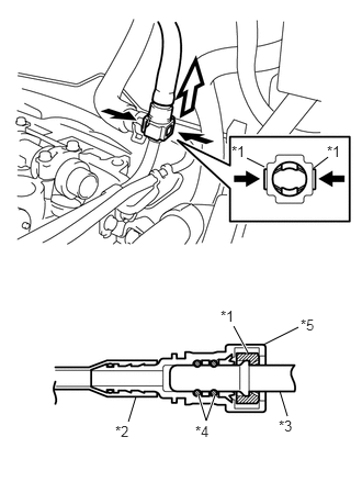
| *1 | Retainer |
| *2 | Nylon Tube |
| *3 | Fuel Delivery Pipe Sub-assembly |
| *4 | O-Ring |
| *5 | Fuel Tube Connector |

|
Pinch |

|
Pull |
Pinch the retainer of the fuel tube connector, and then pull the fuel tube connector off of the fuel delivery pipe sub-assembly.
- NOTICE:
- ·
Check for foreign matter on the fuel tube sub-assembly around the fuel tube connector. Clean it if necessary. Foreign matter can affect the ability of the O-ring to seal the fuel tube connector and fuel delivery pipe sub-assembly.
·Do not use any tools to separate the fuel tube connector and fuel delivery pipe sub-assembly.
·Do not forcibly bend, kink or twist the nylon tube.
·Keep the fuel tube connector and fuel delivery pipe sub-assembly free from foreign matter.
·If the fuel tube connector and fuel delivery pipe sub-assembly are stuck, push and pull to release them.
·Put the fuel tube connector and fuel delivery pipe sub-assembly in plastic bags to prevent damage and contamination.
23807
9.REMOVE FUEL DELIVERY PIPE SUB-ASSEMBLY
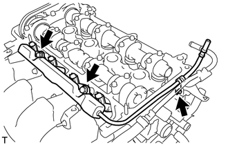
Remove the 3 bolts and fuel delivery pipe sub-assembly together with 4 fuel injector assemblies from the cylinder head sub-assembly.
- NOTICE:
-
Do not drop the fuel injector assemblies when removing the fuel delivery pipe sub-assembly.
23891
10.REMOVE FUEL DELIVERY SPACER
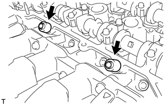
Remove the 2 fuel delivery spacers from the cylinder head sub-assembly.
23291
11.REMOVE INJECTOR VIBRATION INSULATOR
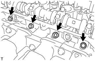
Remove the 4 injector vibration insulators from the cylinder head sub-assembly.
23250
12.REMOVE FUEL INJECTOR ASSEMBLY
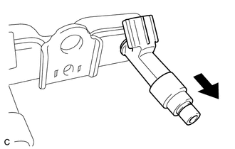
Pull the 4 fuel injector assemblies out of the fuel delivery pipe sub-assembly.
Remove the O-ring from each fuel injector assembly.
- NOTICE:
-
Prevent entry of foreign matter by covering the fuel injector assemblies with plastic bags.
- HINT:
-
For reinstallation, attach a tag or label to each fuel injector assembly shaft.