U340E AUTOMATIC TRANSMISSION / TRANSAXLE PARK / NEUTRAL POSITION SWITCH INSTALLATION
PROCEDURE

 84540
1.INSTALL PARK/NEUTRAL POSITION SWITCH
Temporarily install the park/neutral position switch to the automatic transaxle assembly with the 2 bolts.
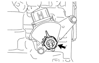
Install a new lock plate and lock nut to the park/neutral position switch.
- Torque:
- 6.9 N*m (70 kgf*cm, 61 in.*lbf)
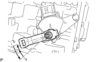
| *a | P Position |
| *b | N Position |
Temporarily install the transmission control shaft lever to the automatic transaxle assembly.
Rotate the transmission control shaft lever counterclockwise until it stops, and then from that position rotate it clockwise by 2 notches to set it to the N position.
Remove the transmission control shaft lever from the automatic transaxle assembly.
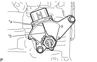
| *a | Neutral Basic Line |
| *b | Protrusion |
Rotate the park/neutral position switch clockwise or counterclockwise to align the neutral basic line with the protrusion as shown in the illustration.
Hold the park/neutral position switch in this position and tighten the 2 bolts.
- Torque:
- 5.4 N*m (55 kgf*cm, 48 in.*lbf)
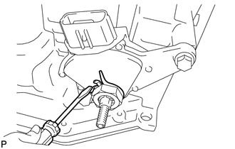
Using a screwdriver, secure the lock nut with the lock plate.
Install the transmission control shaft lever to the automatic transaxle assembly with the washer and nut.
- Torque:
- 12.7 N*m (130 kgf*cm, 9 ft.*lbf)
Connect the connector to the park/neutral position switch.
33820B
2.CONNECT TRANSMISSION CONTROL CABLE ASSEMBLY
- NOTICE:
-
To prevent damage to the transmission control cable assembly and transmission floor shift assembly, connect the automatic transaxle assembly side of the transmission control cable assembly before connecting the transmission floor shift assembly side.
| *a | P Position |
| *b | N Position |
Rotate the transmission control shaft lever counterclockwise until it stops, and then from that position rotate it clockwise by 2 notches to set it to the N position.
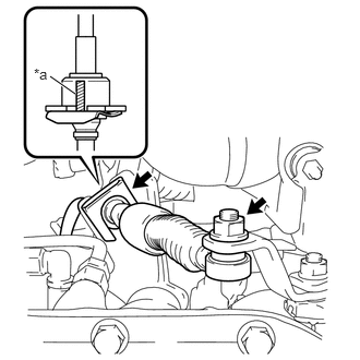
| *a | Paint Mark |
Install the transmission control cable assembly to the No. 1 transmission control cable bracket with a new clip.
- NOTICE:
-
Make sure that the paint mark on the transmission control cable assembly is aligned with the slit in the No. 1 transmission control cable bracket before installing the clip.
Connect the transmission control cable assembly to the transmission control shaft lever with the nut.
- Torque:
- 12 N*m (122 kgf*cm, 9 ft.*lbf)
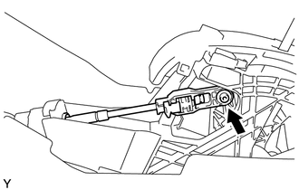
Confirm that the shift lever is in N, and then connect the end of the transmission control cable assembly to the transmission floor shift assembly.
- NOTICE:
- ·
Securely install the end of the transmission control cable assembly to the transmission floor shift assembly.
·Install the end of the transmission control cable assembly so that its adjustment lock section is on the driver side.
3.ADJUST SHIFT LEVER POSITION
4.INSPECT SHIFT LEVER POSITION
84540
5.INSPECT PARK/NEUTRAL POSITION SWITCH
51442C
6.INSTALL ENGINE UNDER COVER LH (w/o Metal Type Under Cover)
51405A
7.INSTALL NO. 1 ENGINE UNDER COVER SUB-ASSEMBLY (w/ Metal Type Under Cover)
51451A
8.INSTALL CENTER ENGINE UNDER COVER (w/ Metal Type Under Cover)
58910C
9.INSTALL REAR CONSOLE BOX ASSEMBLY