CLUTCH CLUTCH MASTER CYLINDER(for LHD) INSTALLATION
PROCEDURE

 31453
1.INSTALL CLUTCH MASTER CYLINDER PUSH ROD CLEVIS
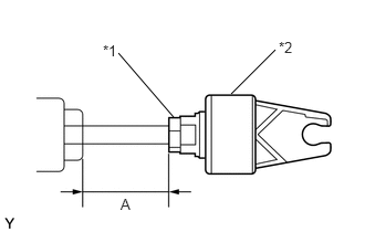
| *1 | Lock Nut |
| *2 | Clutch Master Cylinder Push Rod Clevis |
Install the lock nut to the clutch master cylinder assembly.
Install the clutch master cylinder push rod clevis to the clutch master cylinder assembly.
Tighten the lock nut and check the dimension A is the same as the dimension A that was measured during removal.
- Torque:
- 11.8 N*m (120 kgf*cm, 9 ft.*lbf)
- NOTICE:
-
When tightening the lock nut, be sure to hold the clutch master cylinder push rod clevis in place by its square portion.
31410
2.INSTALL CLUTCH MASTER CYLINDER ASSEMBLY
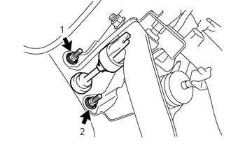
Install the clutch master cylinder assembly to the body with the 2 nuts in the order shown in the illustration.
- Torque:
- 9.0 N*m (92 kgf*cm, 80 in.*lbf)
31453
3.CONNECT CLUTCH MASTER CYLINDER PUSH ROD CLEVIS
31481
4.CONNECT CLUTCH MASTER CYLINDER TO FLEXIBLE HOSE TUBE
Using a 10 mm union nut wrench, connect the clutch master cylinder to flexible hose tube to the clutch master cylinder assembly.
- Torque:
- 15.2 N*m (155 kgf*cm, 11 ft.*lbf)
- NOTICE:
-
Use the formula to calculate special torque values for situations where a union nut wrench is combined with a torque wrench.
-
Click hereGeneral>INTRODUCTION>REPAIR INSTRUCTION>PRECAUTION
31434C
5.CONNECT CLUTCH RESERVOIR TUBE
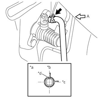
| *a | View A |
| *b | Upper Side of Vehicle |
| *c | Left Side of Vehicle |
| *d | Paint Mark |
Connect the clutch reservoir tube to the clutch master cylinder assembly with the hose clip as shown in the illustration.
- NOTICE:
-
Perform the installation with the hose clip and the paint mark of the clutch reservoir tube at the correct direction.
44610
6.INSTALL BRAKE BOOSTER ASSEMBLY
7.FILL RESERVOIR WITH BRAKE FLUID
8.BLEED CLUTCH LINE
9.INSPECT FOR BRAKE FLUID LEAK
- HINT:
- ·
Check for leakage in the brake system.
·Check for leakage in the clutch system.
10.INSPECT BRAKE FLUID LEVEL IN RESERVOIR
11.INSPECT AND ADJUST CLUTCH PEDAL