U441E AUTOMATIC TRANSMISSION / TRANSAXLE AUTOMATIC TRANSAXLE ASSEMBLY REMOVAL
PROCEDURE

 1. PRECAUTION
- NOTICE:
-
After turning the ignition switch off, waiting time may be required before disconnecting the cable from the battery terminal. Therefore, make sure to read the disconnecting the cable from the battery terminal notice before proceeding with work.
-
Click hereGeneral>INTRODUCTION>REPAIR INSTRUCTION>PRECAUTION
2.DISCONNECT CABLE FROM NEGATIVE BATTERY TERMINAL
- NOTICE:
-
When disconnecting the cable, some systems need to be initialized after the cable is reconnected.
-
Click hereGeneral>INTRODUCTION>REPAIR INSTRUCTION>INITIALIZATION
51442C
3.REMOVE ENGINE UNDER COVER LH (w/o Metal Type Under Cover)
51441C
4.REMOVE ENGINE UNDER COVER RH (w/o Metal Type Under Cover)
51451A
5.REMOVE CENTER ENGINE UNDER COVER (w/ Metal Type Under Cover)
51405A
6.REMOVE NO. 1 ENGINE UNDER COVER SUB-ASSEMBLY (w/ Metal Type Under Cover)
7.DRAIN AUTOMATIC TRANSAXLE FLUID
23827A
8.DISCONNECT NO. 2 FUEL VAPOR FEED HOSE
23820
9.DISCONNECT FUEL VAPOR FEED HOSE ASSEMBLY
17341T
10.DISCONNECT NO. 1 AIR HOSE
17735
11.REMOVE AIR CLEANER CAP WITH NO. 1 AIR CLEANER HOSE
17801
12.REMOVE AIR CLEANER FILTER ELEMENT SUB-ASSEMBLY
17701
13.REMOVE AIR CLEANER CASE SUB-ASSEMBLY
28800
14.REMOVE BATTERY
74431
15.REMOVE BATTERY TRAY
74410
16.REMOVE BATTERY CARRIER ASSEMBLY
58910C
17.REMOVE REAR CONSOLE BOX ASSEMBLY (w/ Console Box Lid)
58910C
18.REMOVE REAR CONSOLE BOX ASSEMBLY (w/o Console Box Lid)
33820B
19.DISCONNECT TRANSMISSION CONTROL CABLE ASSEMBLY
- NOTICE:
-
To prevent damage to the transmission control cable assembly and transmission floor shift assembly, disconnect the transmission floor shift assembly side of the transmission control cable assembly before disconnecting the automatic transaxle assembly side.
Apply the parking brake and move the shift lever to N.
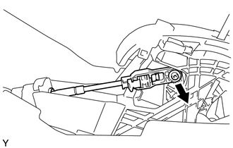
Disconnect the end of the transmission control cable assembly from the transmission floor shift assembly.
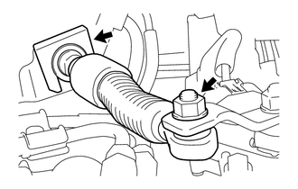
Remove the nut to disconnect the transmission control cable assembly from the transmission control shaft lever.
Remove the clip to separate the transmission control cable assembly from the No. 1 transmission control cable bracket.
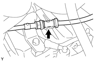
Separate the transmission control cable assembly from the transmission control cable support.
82123
20.DISCONNECT NO. 3 ENGINE WIRE
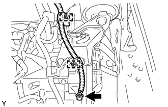
Remove the bolt to disconnect the No. 3 engine wire from the automatic transaxle assembly.
Disengage the 2 clamps to separate the No. 3 engine wire from the engine mounting bracket LH.
82121
21.DISCONNECT ENGINE WIRE
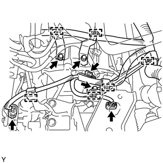
Disconnect the 3 connectors from the automatic transaxle assembly.
Disengage the 6 clamps to separate the engine wire.
Remove the 3 bolts and 3 wire harness clamp brackets from the automatic transaxle assembly.
22.REMOVE FRONT DRIVE SHAFT ASSEMBLIES
28100
23.REMOVE STARTER ASSEMBLY
32941
24.DISCONNECT INLET NO. 1 OIL COOLER HOSE
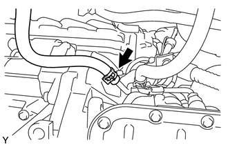
Slide the hose clip and disconnect the inlet No. 1 oil cooler hose from the inlet No. 1 oil cooler tube.
32942
25.DISCONNECT OUTLET NO. 1 OIL COOLER HOSE
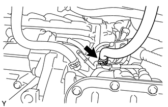
Slide the hose clip and disconnect the outlet No. 1 oil cooler hose from the outlet No. 1 oil cooler tube.
11361J
26.REMOVE FLYWHEEL HOUSING UNDER COVER
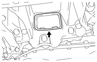
Remove the flywheel housing under cover from the engine assembly.
32101A
27.REMOVE DRIVE PLATE AND TORQUE CONVERTER ASSEMBLY SETTING BOLT
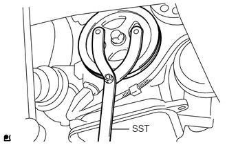
Using SST, hold the crankshaft pulley.
- SST
- 09960-10010 (09962-01000, 09963-01000)
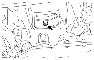
Remove the 6 drive plate and torque converter assembly setting bolts.
51201
28.REMOVE FRONT SUSPENSION CROSSMEMBER SUB-ASSEMBLY
29.SUPPORT ENGINE ASSEMBLY
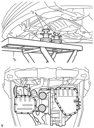
| *a | Attachment |
| *b | Engine Lifter |

|
Attachment Placement Positions |
Place the height adjustment attachments or plate lift attachments in the positions shown in the illustration and set the engine lifter underneath the engine assembly.
- NOTICE:
- ·
Place the height adjustment attachments or plate lift attachments so that the engine assembly with the automatic transaxle assembly is level.
·As the engine assembly with the automatic transaxle assembly is very heavy, be sure to support it securely.
·To prevent deformation of the No. 2 oil pan sub-assembly, never set any attachments against the No. 2 oil pan sub-assembly of the engine assembly.
·To prevent deformation of the automatic transaxle oil pan sub-assembly, never set any attachments against the automatic transaxle oil pan sub-assembly.
12321B
30.REMOVE DRIVE SHAFT HEAT INSULATOR SUB-ASSEMBLY
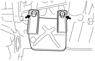
Using a 12 mm deep socket wrench, remove the nut.
Remove the bolt and drive shaft heat insulator sub-assembly from the engine assembly.
12364B
31.REMOVE NO. 2 ENGINE MOVING CONTROL ROD
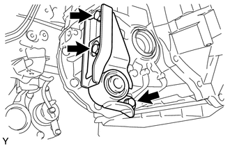
Remove the 3 bolts and No. 2 engine moving control rod from the automatic transaxle assembly.
30500
32.REMOVE AUTOMATIC TRANSAXLE ASSEMBLY
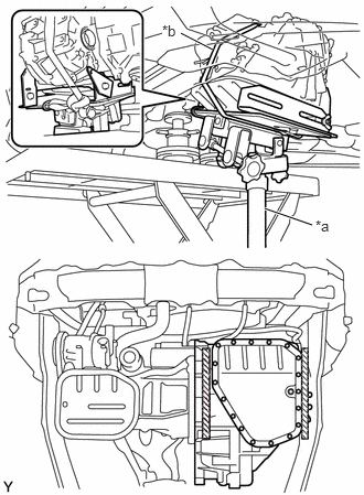
| *a | Transmission Jack |
| *b | Lashing Belt |
|
|
Attachment Placement Positions |
On a flat location, set the attachments in the positions shown in the illustration and set the transmission jack underneath the automatic transaxle assembly.
- NOTICE:
- ·
To prevent deformation of the automatic transaxle oil pan sub-assembly, never set any attachments against the automatic transaxle oil pan sub-assembly.
·Secure the automatic transaxle assembly to the transmission jack with a lashing belt, etc., to prevent the automatic transaxle assembly from falling.
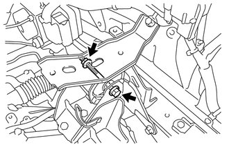
Remove the bolt and nut to separate the engine mounting bracket LH from the engine mounting insulator LH.
- HINT:
-
Turn the bolt while holding the nut.
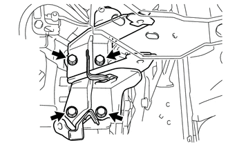
Remove the 4 bolts and engine mounting bracket LH from the automatic transaxle assembly.
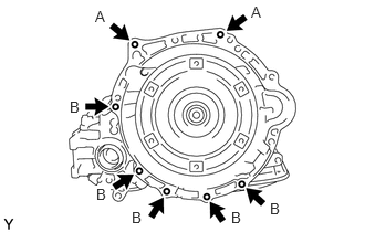
Remove the 7 bolts and automatic transaxle assembly from the engine assembly.
- NOTICE:
- ·
Make sure that the engine assembly is not tilted.
·To prevent damage to the knock pins, do not pry between the automatic transaxle assembly and engine assembly.
·Do not allow the torque converter assembly to fall off.
- HINT:
- ·
Bolt A: Remove from automatic transaxle assembly side
·Bolt B: Remove from engine assembly side
33.REMOVE TORQUE CONVERTER ASSEMBLY
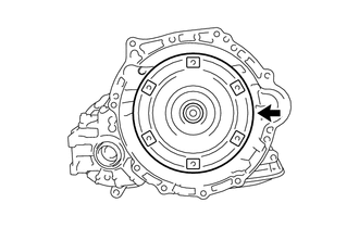
Remove the torque converter assembly from the automatic transaxle assembly.
- NOTICE:
-
Remove the torque converter assembly from the input shaft horizontally.
33823
34.REMOVE NO. 1 TRANSMISSION CONTROL CABLE BRACKET
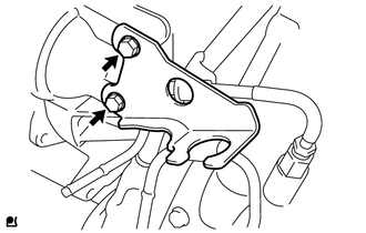
Remove the 2 bolts and No. 1 transmission control cable bracket from the automatic transaxle assembly.
33829
35.REMOVE TRANSMISSION CONTROL CABLE SUPPORT
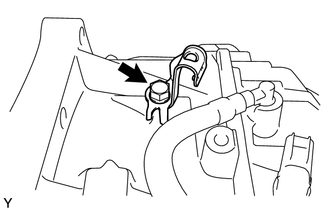
Remove the bolt and transmission control cable support from the automatic transaxle assembly.
32921
36.DISCONNECT INLET NO. 1 OIL COOLER TUBE
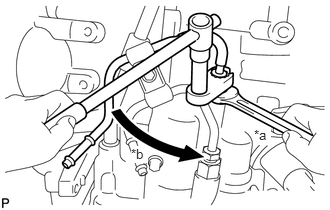
| *a | Hold |
| *b | Turn |
Using a 14 mm union nut wrench, disconnect the inlet No. 1 oil cooler tube while holding the oil cooler tube union with a wrench.
32922
37.DISCONNECT OUTLET NO. 1 OIL COOLER TUBE
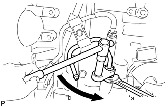
| *a | Hold |
| *b | Turn |
Using a 14 mm union nut wrench, disconnect the outlet No. 1 oil cooler tube while holding the oil cooler tube union with a wrench.
32924
38.REMOVE NO. 2 OIL COOLER TUBE CLAMP
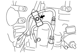
Remove the bolt and No. 2 oil cooler tube clamp from the transmission oil filler tube sub-assembly.
Remove the inlet No. 1 oil cooler tube and outlet No. 1 oil cooler tube from the automatic transaxle assembly.
35103
39.REMOVE TRANSMISSION OIL LEVEL DIPSTICK SUB-ASSEMBLY
Remove the transmission oil level dipstick sub-assembly from the transmission oil filler tube sub-assembly.
35013
40.REMOVE TRANSMISSION OIL FILLER TUBE SUB-ASSEMBLY
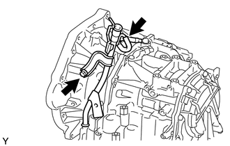
Disconnect the breather hose from the transmission oil filler tube sub-assembly.
Remove the bolt and transmission oil filler tube sub-assembly from the automatic transaxle assembly.
Remove the O-ring from the transmission oil filler tube sub-assembly.
33403M
41.REMOVE SPEEDOMETER DRIVEN HOLE COVER SUB-ASSEMBLY
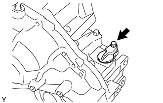
Remove the bolt and speedometer driven hole cover sub-assembly from the automatic transaxle assembly.
Remove the O-ring from the speedometer driven hole cover sub-assembly.