BRAKE CONTROL / DYNAMIC CONTROL SYSTEMS ANTI-LOCK BRAKE SYSTEM TC and CG Terminal Circuit
DESCRIPTION
Connecting terminals 13 (TC) and 4 (CG) of the DLC3 causes the ECU to display the DTC by blinking the ABS warning light.
WIRING DIAGRAM
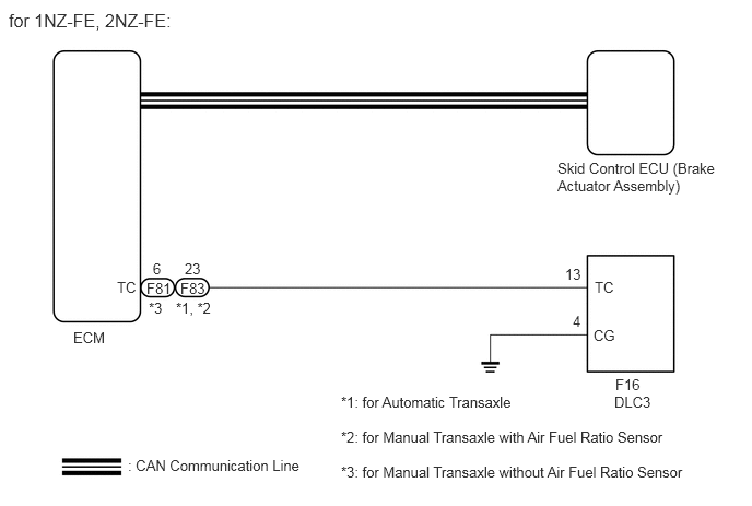
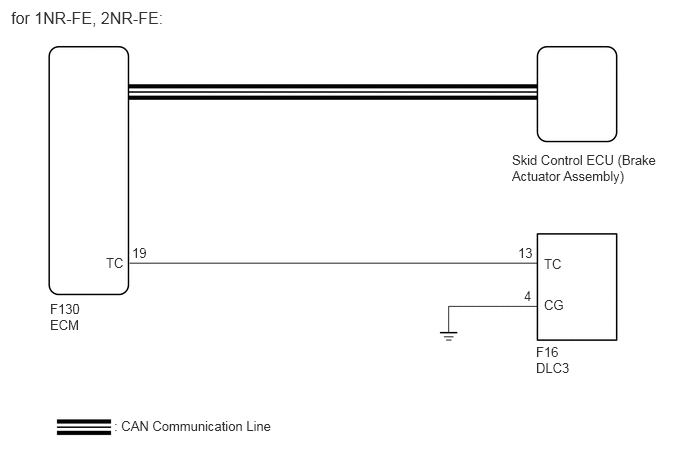
- HINT:
-
When the warning lights continue to blink, a ground short in the wiring of terminal 13(TC) of the DLC3 or an internal ground short in one or more ECUs is suspected.
CAUTION / NOTICE / HINT
- NOTICE:
-
When replacing the skid control ECU (brake actuator assembly), perform reset memory, deceleration sensor zero point calibration and CVT oil pressure calibration (for CVT).
for 1NR-FE
Click hereDrivetrain>K411 CVT>CONTINUOUSLY VARIABLE TRANSAXLE SYSTEM>INITIALIZATION
for 2NR-FE
Click hereDrivetrain>K312 CVT>CONTINUOUSLY VARIABLE TRANSAXLE SYSTEM>INITIALIZATION
PROCEDURE
Check if CAN communication system DTCs are output.
Click herePower Source / Network>NETWORKING>CAN COMMUNICATION SYSTEM>DIAGNOSIS SYSTEM
- Result:
Result Proceed to DTC is not output A DTC is output B
A
B
Click herePower Source / Network>NETWORKING>CAN COMMUNICATION SYSTEM>HOW TO PROCEED WITH TROUBLESHOOTING
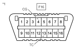
| *1 | DLC3 |
Turn the ignition switch to ON.
Measure the voltage according to the value(s) in the table below.
- Standard Voltage:
Tester Connection Switch Condition Specified Condition F16-13 (TC) - F16-4 (CG) Ignition switch ON 11 to 14 V
- Result:
Result Proceed to NG A OK B
A
B
for 1NZ-FE, 2NZ-FE
Turn the ignition switch off.
Disconnect the F81*1 or F83*2, *3 ECM connector.
*1: for Manual Transaxle without Air Fuel Ratio Sensor
*2: for Automatic Transaxle
*3: for Manual Transaxle with Air Fuel Ratio Sensor
Measure the resistance according to the value(s) in the table below.
- Standard Resistance:
for Manual Transaxle without Air Fuel Ratio Sensor Tester Connection Condition Specified Condition F16-13 (TC) - F81-6 (TC) Always Below 1 Ω F16-13 (TC) or F81-6 (TC) - Body ground Always 10 kΩ or higher
for Automatic Transaxle or for Manual Transaxle with Air Fuel Ratio Sensor Tester Connection Condition Specified Condition F16-13 (TC) - F83-23 (TC) Always Below 1 Ω F16-13 (TC) or F83-23 (TC) - Body ground Always 10 kΩ or higher
Reconnect the F81*1 or F83*2, *3 ECM connector.
*1: for Manual Transaxle without Air Fuel Ratio Sensor
*2: for Automatic Transaxle
*3: for Manual Transaxle with Air Fuel Ratio Sensor
for 1NR-FE, 2NR-FE
Turn the ignition switch off.
Disconnect the F130 ECM connector.
Measure the resistance according to the value(s) in the table below.
- Standard Resistance:
Tester Connection Condition Specified Condition F16-13 (TC) - F130-19 (TC) Always Below 1 Ω F16-13 (TC) or F130-19 (TC) - Body ground Always 10 kΩ or higher
Reconnect the F130 ECM connector.
- Result:
Proceed to OK NG
OK
NG
Measure the resistance according to the value(s) in the table below.
- Standard Resistance:
Tester Connection Condition Specified Condition F16-4 (CG) - Body ground Always Below 1 Ω
- Result:
Proceed to OK NG
OK
NG
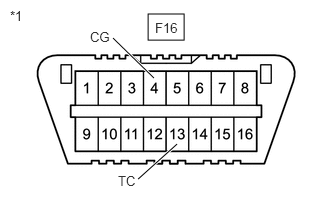
| *1 | DLC3 |
Turn the ignition switch off.
Using SST, connect terminals TC and CG of the DLC3.
- SST
- 09843-18040
Turn the ignition switch to ON.
Check that the malfunction indicator lamp is blinking.
- Result:
Result Proceed to MIL is blinking A MIL is not blinking 1NZ-FE (for Automatic Transaxle) B 1NZ-FE (for Manual Transaxle) C 1NZ-FE (w/ Air Fuel Ratio Sensor) D 2NZ-FE (for Automatic Transaxle) E 2NZ-FE (for Manual Transaxle) F 1NR-FE G 2NR-FE H
A
B
C
D
E
F
G
Click hereEngine / Hybrid System>1NR-FE ENGINE CONTROL>SFI SYSTEM>HOW TO PROCEED WITH TROUBLESHOOTING
H
Click hereEngine / Hybrid System>2NR-FE ENGINE CONTROL>SFI SYSTEM>HOW TO PROCEED WITH TROUBLESHOOTING